NI PXI-2501/2503 2-Wire Quad 6×1 Multiplexer Topology
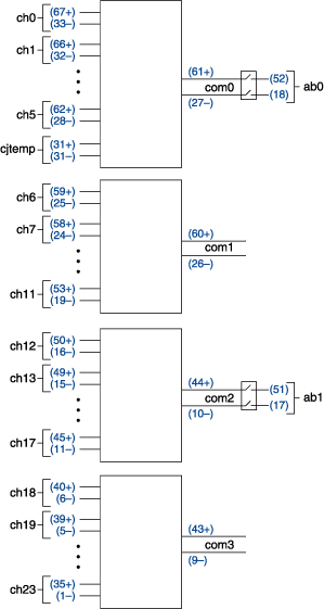
When using the NI PXI-2501/2503 as a 2-wire quad 6×1 multiplexer, connect your signals using the NI TB-2605 terminal block. In this topology, you can connect to a Cold-Junction Sensor Channel for cold-junction compensation. The following figure is a representation of the NI PXI-2501/2503 in this mode.
 |
 |
Making a Connection
The NI PXI-2501/2503 in this topology contains four banks of six 2-wire input channels connected to a common 2-wire channel. These input channels are referred to as ch<0..23>, and the four common channels are referred to as com<0..3>. You can only connect to the common channel that is in the same bank. The banks are organized as follow:
| Input Channels | Common Channel |
|---|---|
| ch0, ch1, ch2, ch3, ch4, ch5, cjtemp | com0 |
| ch6, ch7, ch8, ch9, ch10, ch11 | com1 |
| ch12, ch13, ch14, ch15, ch16, ch17 | com2 |
| ch18, ch19, ch20, ch21, ch22, ch23 | com3 |
For example, you can connect ch5 to com0; however, you cannot connect ch5 to com1 in this topology. When connecting signals for ch5, you would connect them to screw terminals 62 and 28 for HI and LO of the signal, respectively. For com0, connect to screw terminals 61 and 27 for HI and LO of the signal, respectively.
Notice that in the first bank you can connect cjtemp to com0. This connects com0 to a temperature sensor on the NI TB-2605 terminal block. Refer to Cold-Junction Sensor Channel for more information.
You can connect the channels of the NI PXI-2501/2503 using the niSwitch Connect Channels VI or the niSwitch_Connect function. For example, to connect channel 5 to common 0, call the niSwitch Connect Channels VI or the niSwitch_Connect functioning the channel 1 parameter set to ch5 and the channel 2 parameter set to com0. To connect channel 5 to ab0, make an additional call to the niSwitch Connect Channels VI or the niSwitch_Connect function to connect com1 to ab0.
When scanning PXI-2501/2503, a typical scan list entry could be ch7->com1;. This entry routes the signal connected to ch7 to com1.
Pinout
The following figure identifies the pins for the NI PXI-2501/2503 in the 2-wire quad 6×1 multiplexer topology.
