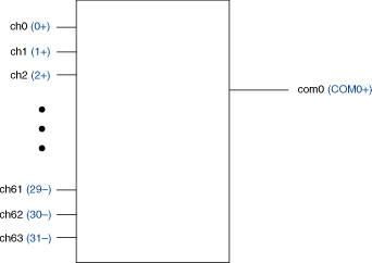
NI PXI-2527 1-Wire 64×1 Multiplexer Topology
Connect to the pins of the NI TB-2627 terminal block to use the NI PXI-2527 as a 1-wire 64×1 multiplexer. In this topology, all channel terminals (CH0 through CH63) route to both COM0+ and COM1+. The 1WREF0 lead is connected to COM0–, and the 1WREF1 lead is connected to COM1–. The pair COM0+ and COM0– is addressed as com0 in software, and the pair COM1+ and COM1– is addressed as com1 in software. In this topology, COM0+ is connected to COM1+.
The following figure represents the NI PXI-2527 in the 1-wire 64×1 multiplexer topology.
 |
 |
Making a Connection
Both the scanning command, ch2->com0;, and the immediate operation, niSwitch Connect Channels VI or the niSwitch_Connect function with parameters ch2 and com0, result in the following connections:
signal connected to CH2+ is routed to COM0+
Pinout
The following figure and table identify the pins for the NI PXI-2527 in the 1-wire 64×1 multiplexer topology.
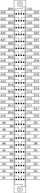
| Software Name | Pin Number | Software Name | Pin Number |
|---|---|---|---|
| ch0 | A1 | ch36 | B3 |
| ch1 | D1 | ch37 | C3 |
| ch2 | A2 | ch38 | B4 |
| ch3 | D2 | ch39 | C4 |
| ch4 | A3 | ch40 | B5 |
| ch5 | D3 | ch41 | C5 |
| ch6 | A4 | ch42 | B6 |
| ch7 | D4 | ch43 | C6 |
| ch8 | A5 | ch44 | B7 |
| ch9 | D5 | ch45 | C7 |
| ch10 | A6 | ch46 | B8 |
| ch11 | D6 | ch47 | C8 |
| ch12 | A7 | ch48 | B10 |
| ch13 | D7 | ch49 | C10 |
| ch14 | A8 | ch50 | B11 |
| ch15 | D8 | ch51 | C11 |
| ch16 | A10 | ch52 | B12 |
| ch17 | D10 | ch53 | C12 |
| ch18 | A11 | ch54 | B13 |
| ch19 | D11 | ch55 | C13 |
| ch20 | A12 | ch56 | B14 |
| ch21 | D12 | ch57 | C14 |
| ch22 | A13 | ch58 | B15 |
| ch23 | D13 | ch59 | C15 |
| ch24 | A14 | ch60 | B16 |
| ch25 | D14 | ch61 | C16 |
| ch26 | A15 | ch62 | B17 |
| ch27 | D15 | ch63 | C17 |
| ch28 | A16 | 1wref0 | C9 |
| ch29 | D16 | 1wref1 | C18 |
| ch30 | A17 | com0+ | A9 |
| ch31 | D17 | com0– | B9 |
| ch32 | B1 | com1+ | A18 |
| ch33 | C1 | com1– | B18 |
| ch34 | B2 | cjtemp+ | A25 |
| ch35 | C2 | cjtemp– | D25 |