Capacitance
Electrical lifetime specifications for reed relays often assume a resistive load. Other factors such as board traces and external cables can contribute additional capacitance. When a relay closes, this capacitance acts as a transient short circuit until it is recharged. These short circuits generate high inrush currents that are usually much larger than the steady state current and can damage the relay.
Determining the maximum allowable capacitance is dependent on the application where reed relays are used. Relay vendors cannot be more specific about the maximum allowable capacitance because many factors external to the relay affect inrush current.
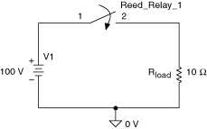
The following figure shows a purely resistive system. When the relay closes, current flows that is proportional to the source voltage V1 and the load resistance Rload.
Ideal Resistive System
 |
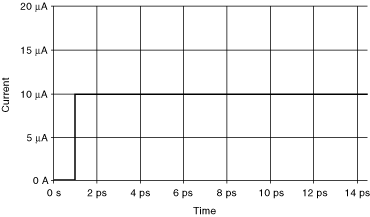
The following figure shows current flowing through the relay.
Resistive Load Switching
 |
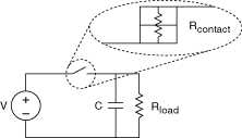
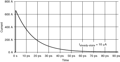
A more realistic system is shown in the following figure. The relay contact has a non-zero resistance, Rcontact and an output load capacitance, C. When the relay closes an inrush current, limited only by Rcontact, flows through the contacts to charge the capacitor. If the inrush current is much larger than the intended steady state current, the current decreases to the steady state. The time for the inrush current to decrease to the steady state is dependent on the time constant defined by Rcontact and C.
More Realistic System
 |
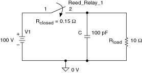 |
The peak inrush current shown in the following figure is much higher than the peak inrush of the ideal resistive system example.
Capacitive Load Switching ( =RcontactC)
 |