NI SCXI-1127/1128 4-Wire 16×1 Multiplexer Topology
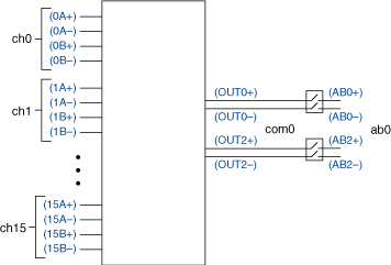
When using the NI SCXI-1127/1128 as a 4-wire 16×1 multiplexer, connect your signals using the NI SCXI-1331 terminal block. In this topology, use the line labeled 4W inside the NI SCXI-1331 terminal block. The following figure represents the NI SCXI-1127/1128 in the 4-wire 16×1 multiplexer topology.
 |
 |
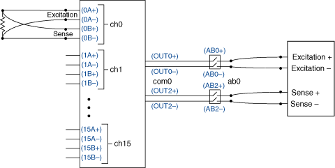
4-wire mode is usually used for 4-wire resistance measurements. One pair of wires supplies the excitation current while the other pair makes the voltage measurement. In 4-wire mode, connect your excitation or source leads to xA+ and xA- and connect your measurement or sensing leads to xB+ and xB-.
 |
 |
 |
Note The previous figure shows the DMM connected to the high-voltage analog bus (HVAB) of the switch module. You can also connect the DMM to the terminal block. If you use the terminal block, connect OUT0+ and OUT0- to the excitation terminals of the DMM and connect OUT2+ and OUT2- to the sense terminals of the DMM. |
Making a Connection
During scanning, a typical scan list entry is ch2->com0;. This entry routes, by default, excitation signals from 2A± to OUT0± to AB0±. This entry also routes the sensing lead from 2B± to OUT2± to AB2±.
When using the niSwitch Connect Channels VI or the niSwitch_Connect function with ch2 and com0 during immediate operations, the signals connected to 2A± are routed to OUT0± and the signals connected to 2B± are routed to OUT2±. To route OUT0± to AB0± and OUT2± to AB2±, use the niSwitch Connect Channels VI or the niSwitch_Connect function with com0 and ab0 to make both connections.
Pinout
The following figure identifies the pins for the NI SCXI-1127/1128 in the 4-wire 16×1 multiplexer topology.
