Current-Loop Receiving
From NI Switches
Current-Loop Receiving
This topic describes how to customize your NI SCXI-1127/1128 module for current-loop receiving. The NI SCXI-1127/1128 modules have unused component spaces on the PCB for transforming individual channels to current-to-voltage converters. NI offers a process-current pack of four 249 Ω, 0.1%, 5 ppm, 0.25 W resistors. The reference designator format for the current-loop resistors is such that input channel x corresponds to the resistor reference designator RCLx. For example, the resistor pad for channel 14 is RCL14.
| Caution Before installing the resistors in your module, disconnect all signals from your switch module. |
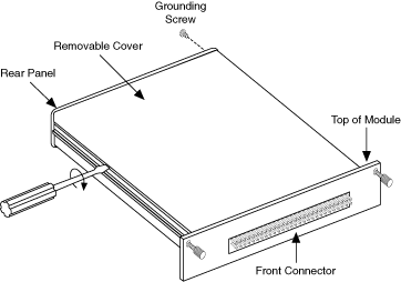
Before installing your module in the SCXI chassis, install the resistors by performing the following steps while referring to the following figure:
- Ground yourself using a grounding strap or a ground connected to your SCXI chassis. Properly grounding yourself prevents damage to your SCXI module from electrostatic discharge.
- Remove the grounding screw from the top cover.
- Snap out the top cover of the shield by placing a screwdriver in the groove at the bottom of the module and pushing down.
- Remove the rear panel by unscrewing the two remaining screws.
- Slide the module out of its enclosure.
- Bend and trim the resistor lead as shown in the following figure. Be sure that the resistor does not extend more than 0.5 in. above the surface of the circuit board and that the leads do not protrude through the bottom of the board by more than 0.060 in.

- Insert the resistor into the appropriate socket, labeled RCLx.
- Solder the leads to the pad on the bottom side of the module.
- Slide the module back into its enclosure.
- Install the hex bracket screw.
- Install the rear panel.
- Install the top cover and grounding screw.