NI SCXI-1193 Quad 8×1 Multiplexer Topology
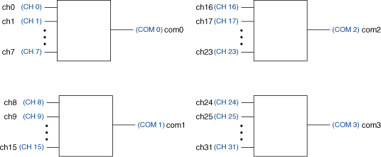
The following figure represents the NI SCXI-1193 quad 8×1 multiplexer topology.
 |
 |
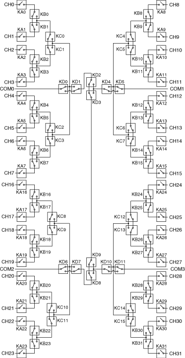
The following figure shows the reset position of the NI SCXI-1193 in the quad 8×1 multiplexer topology. The reset position is the power-on configuration of the module.

Making a Connection
The NI SCXI-1193 in this topology contains four banks of eight input channels connected to a common channel. These input channels are referred to as ch<0..31>, and the four common channels are referred to as com<0..3>. You can only connect to the common channel that is in the same bank. The banks are organized as follows:
| Input Channels | Common Channel |
|---|---|
| ch0, ch1, ch2, ch3, ch4, ch5, ch6, ch7 | com0 |
| ch8, ch9, ch10, ch11, ch12, ch13, ch14, ch15 | com1 |
| ch16, ch17, ch18, ch19, ch20, ch21, ch22, ch23 | com2 |
| ch24, ch25, ch26, ch27, ch28, ch29, ch30, ch31 | com3 |
For example, you can connect ch8 to com1; however, you cannot connect ch8 to com0 in this topology.
You can connect the channels of the NI SCXI-1193 using the niSwitch Connect Channels VI or the niSwitch_Connect function. For example, to connect channel 16 to common 2, call the niSwitch Connect Channels VI or the niSwitch_Connect function with the channel 1 parameter set to ch16 and the channel 2 parameter set to com2.
When scanning the NI SCXI-1193, a typical scan list entry could be ch2->com0;. This entry routes the signal from ch2 to com0.