Board Layout and Topology
The open contact capacitance of a single reed relay is often very low (< 1 pF), and cannot store enough energy to damage the relay when switching at the rated voltage. The amount of capacitance across an open relay is directly related to the topology of the switch, the layout of the PCBs, and the loads connected to the switch module.
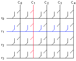
Topologies with long traces and many connected relays, such as matrices, have higher capacitances than simpler topologies.
Matrix Topology
Multiplexer Topology
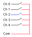
Equivalent Circuit

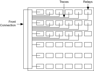
Most instrumentation switches have arrays of relays on a circuit board and a connector on one side. All of the traces must route to the connector. Dense, parallel routes on a PCB increase capacitance between the traces.
Dense Signal Routing Increases Parasitic Capacitance
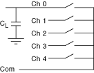
Connecting large capacitive loads directly to the switch terminals or connecting multiple terminals together can substantially increase the load capacitance.
Capacitive Load Connected to a Multiplexer Channel
Multiplexer with 2 Inputs Tied Together
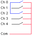
Equivalent Circuit of 2 Multiplexer Channels Tied Together
