NI SCXI-1130 Relay Replacement
The NI SCXI-1130 uses electromechanical reed relays.
Refer to the following table for information about ordering replacement relays.
| Relay Manufacturer | Part |
|---|---|
| Meder | MS05-1A71-75DHR |
Complete the following sets of steps to disassemble your switch module, replace a failed relay, and reassemble your switch module.
Disassemble the Switch Module
- Ground yourself using a grounding strap or a ground connected to your SCXI chassis.

Note Properly grounding yourself prevents damage to your switch module from electrostatic discharge. - Remove the three rear screws from the back of the switch module.
- Carefully remove the top cover of the switch module using a flathead screwdriver.
- Remove the rear panel.
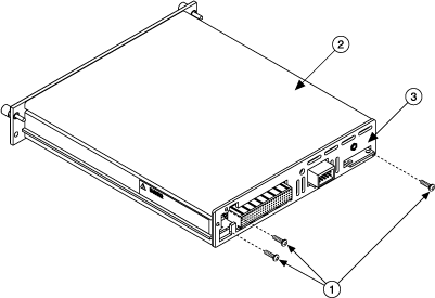
1 Rear Screws 2 Top Cover 3 Rear Panel - Remove the four screws holding the front connectors and the daughterboard assemblies to the front panel.
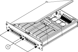
1 Screws - Remove the daughterboard assembly interconnect flat cable.
- Refer to the following figures to locate the relay you want to replace.

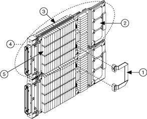
Note The NI SCXI-1130 has two daughterboard assemblies: a top daughterboard assembly and a bottom daughterboard assembly. The top daughterboard assembly is circled in the figure above. Both top and bottom daughterboard assemblies are comprised of two daughterboards: a front daughterboard and a back daughterboard. The relay driver chips are attached to the front daughterboards. Back Daughterboard, Top Assembly
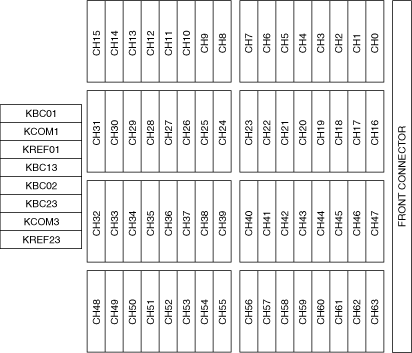
Front Daughterboard, Top Assembly
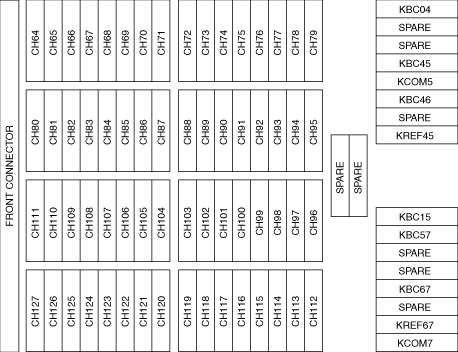
Back Daughterboard, Bottom Assembly
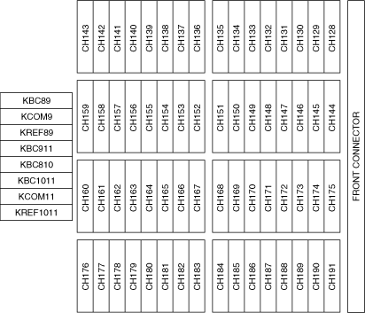
Front Daughterboard, Bottom Assembly
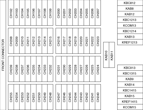
- Remove the four screws that secure the daughterboard assembly to the switch assembly.
- Remove the insulator and spacers that separate the front and back daughterboards.
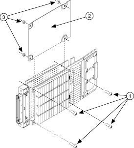
1 Screws 2 Insulator 3 Spacers - To access the daughterboards, disconnect the PCB interconnect cable by lifting the PCB cable latch on the J1 connector.
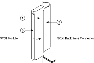
1 PCB Interconnect Cable 2 PCB Cable Latch 3 J1 Connector - Carefully disconnect connectors J7 and J1 on the bottom daughterboard from connectors J8 and J1, respectively, on the top daughterboard.
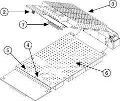
1 J7 Connector 2 J1 Connector 3 Bottom Daughterboard 4 J8 Connector 5 J1 Connector 6 Top Daughterboard
 |
||||||||||||
|
Replace the Relay
Make sure you have the following:
- Temperature-regulated soldering iron set to 300 °C
- 60/40 Lead/Tin solder (flux core)
- Solder wick
- Isopropyl alcohol
- Cotton swabs
Replace the relay as you would any other through-hole part.
Reassemble the Switch Module
Complete the Disassemble the Switch Module steps in reverse order to reassemble your switch module.
 |
Tip In NI-SWITCH 3.1 or later, you can use the Switch Soft Front panel to reset the relay count after you have replaced a failed relay. |