Controlling and Triggering an SCXI Switch
SCXI switch modules require a dedicated switch controller, often cabled to the switch using an backplane adapter.
 |
Note PXI switches are controlled by the PXI chassis controller and do not require a dedicated switch controller. |
In SCXI switch scanning, the switch controller is the liaison between the application development environment (ADE) and the switch module. Using the SCXI protocol, the switch controller communicates with the switch to set the parameters selected in the program and download the scan list to the switch memory. A triggering device advances the scan list through its entries.
The switch controller and the triggering device can be, but are not necessarily, the same device. While you can use an NI DMM as a switch controller and/or a triggering device, the NI 4021 does not have triggering capabilities and can only be used as a switch controller. When controlling an SCXI switch with an NI 4021, use a measurement device, such as an NI DMM, to trigger the switch. The controller, the cabling scheme, and the SCXI switches dictate the scanning capabilities.
The following cables control or trigger SCXI switches and can connect to an SCXI backplane adapter:
SH9MD-AUX Cable
The SH9MD-AUX cable, as shown in the following figure, carries SCXI communication from a switch controller (NI 4021, DMM, E Series, or M Series device) to an SCXI switch module.

The following table lists the functionality of an SH9MD-AUX cable when used with specific SCXI switch controllers.
| Controller | Functionality | Scanning Supported |
|---|---|---|
| NI 4060 | SCXI communication and measurement complete (MC) signal | synchronous scanning |
| NI 407x/4065 | SCXI communication, MC signal, and scanner advanced (SA) signal | synchronous scanning and handshaking |
| NI 4021 | SCXI communication | N/A |
USB Cable
The USB cable, as shown in the following figure, controls an SCXI switch module when used with an NI USB-1359/1358/1357 kit. Refer to the NI Switches Getting Started Guide and the NI 1357/1358/1359 SCXI Controller/Adapter Kit Installation Guide for more information about USB switch control.

AUX Trigger Cable
The AUX trigger cable, as shown in the following figure, separates two triggers (MC and EXT TRIG IN) from an NI DMM. These triggers connect to a switch module terminal block or front panel. The branch of the AUX trigger cable labeled VOLTMETER COMPLETE carries the MC signal from the DMM. The other branch, labeled EXT TRIG IN, carries the SA signal from the switch to the DMM. Use the AUX trigger cable between a PCI or PXI DMM and a PXI or SCXI switch.
 |
Note Using an AUX trigger cable, a DMM can send and receive triggers but cannot control SCXI switches. |

SCXI Backplane Adapters
To cable a switch controller to a switch module using an SH9MD-AUX cable, SCXI switches require an SCXI backplane adapter. For example, DMMs and NI 4021 switch controllers require an NI SCXI-1359/1358/1357 adapter kit to connect to an SCXI switch module. For information about SCXI switch controller/switch module compatibility and to identify the adapter kit(s) required for cabling, refer to the NI Switches Getting Started Guide.
An SCXI backplane adapter routes signals from the SH9MD-AUX cable to the back of the switch in the rightmost position of the chassis. If you are using an NI SCXI-1127/1128/1129/1175, use a backplane adapter to share high-voltage signals among all SCXI switch modules. Unlike digital signals from the SH9MD-AUX or USB cable that are routed to only one SCXI switch, the high-voltage signals are shared among all switches connected to the backplane. Additionally, you can use an HV8-BAN4 cable to connect an SCXI backplane to a DMM and route high-voltage signals to a DMM.
 |
Note In multiple module scanning, only one SCXI switch must be connected to the switch controller or triggering device. |
NI offers SCXI and USB versions of the 1357, 1358, and 1359 backplane adapter kits that can connect from two to eight SCXI switches. Visit ni.com for information about the NI 1357/1358/1359 SCXI Controller/Adapter Kit.
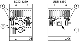
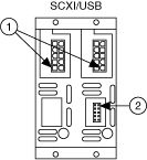
The following figure represents the front view of a 2-slot backplane adapter/controller.
 |
||||||||
|
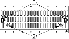
The following figure represents the rear view of a 2-slot backplane adapter/controller.
 |
||||||
|
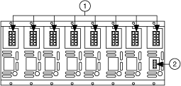
The following figure represents the front view of an 8-slot backplane adapter.
 |
||||||
|
The following figure represents the rear view of an 8-slot backplane adapter.
 |
||||||
|