NI PXI-2566 Relay Replacement
From NI Switches
NI PXI-2566 Relay Replacement
The NI PXI-2566 uses electromechanical armature relays.
Refer to the following table for information about ordering replacement relays.
| Relay Manufacturer | Part Number |
|---|---|
| Aromat (NAiS) | TQ2SA-5V |
Complete the following sets of steps to disassemble your module, replace a failed relay, and reassemble your module.
Disassemble the Module
- Ground yourself using a grounding strap or a ground connected to your PXI chassis.

Note Properly grounding yourself prevents damage to your module from electrostatic discharge. - Locate the relay you want to replace. Refer to the following figure for relay locations.
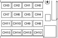
- To replace the CH4 through CH11 relays, refer to Replace the Relay.
To replace all other relays, continue on to step 4. - Remove the screw and washer connecting the daughterboard and topside insulator to the CMI bracket.
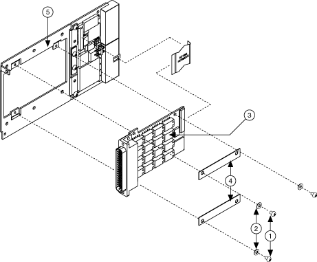
1 Daughterboard and topside insulator screws 2 Daughterboard and topside insulator washers 3 Daughterboard 4 Topside insulator 5 CMI bracket - Remove the topside insulator from the CMI bracket.
- Reconnect the daughterboard to the CMI bracket using the screw and washer from step 4.
Replace the Relay
Before you begin, make sure you have the following items:
- Temperature-regulated soldering iron set to 300 °C
- 60/40 Lead/Tin solder (flux core)
- Solder wick
- Fine pick
- Isopropyl alcohol
- Cotton swabs
If you have a surface mount rework station, replace the relay as you would any other surface mount part. Otherwise, complete the following steps to replace the relay:
- Use the soldering iron and solder wick to remove as much solder from the relay pads as possible. Do not leave the soldering iron on any lead for more than 5 seconds.
Note If it is necessary to reapply the soldering iron to the pad, allow the connection to cool completely before reapplying the soldering iron. - Apply heat to the pads one at a time, and use the pick to gently pry the relay pins from the pads. Make sure that the solder is molten before prying.

Caution Using excessive force on a soldered pad can result in lifting the PCB trace and ruining the daughterboard. - Remove the relay.
- Clean the pads with isopropyl alcohol and cotton swabs.
- Place the new relay on the PCB pads and solder.
- Remove the excess flux with isopropyl alcohol and cotton swabs.
Caution Do not use flux remover to clean the board after relay replacement.
Reassemble the Module
- Remove the screw and washer (from step 6) connecting the daughterboard to the CMI bracket.
- Install the new topside insulator. Refer to the previous figure for the appropriate location.
- Reconnect the daughterboard to the CMI bracket using the screw and washer from step 1. Torque the screw to 2.7 in.-lbs.
| Tip In NI-SWITCH 3.1 or later, you can use the Switch Soft Front panel to reset the relay count after you have replaced a failed relay. |