NI SCXI-1160/1161 Contact Protection for Inductive Load Connections
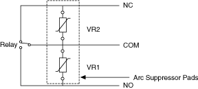
The NI SCXI-1160/1161 modules contain pads on which you can place an arc suppressor protection circuit to limit the voltage spike generated during the switching of inductive loads. These pads are located between the COM position and the NO position and between the COM position and the NC position of the relays.
To determine where to place each arc suppressor, refer to the two tables below, which indicate the channel and suppressor pad assignments.
COM to NO Arc Suppressor Placement
| COM to NO Channel Number | Transient Voltage Suppressor Reference Designator |
|---|---|
| 0 | VR1 |
| 1 | VR3 |
| 2 | VR5 |
| 3 | VR7 |
| 4 | VR9 |
| 5 | VR11 |
| 6 | VR13 |
| 7 | VR15 |
| 8* | VR17 |
| 9* | VR19 |
| 10* | VR21 |
| 11* | VR23 |
| 12* | VR25 |
| 13* | VR27 |
| 14* | VR29 |
| 15* | VR31 |
| * Applies only to NI SCXI-1160. | |
COM to NC Arc Suppressor Placement
| NC to COM Channel Number | Transient Voltage Suppressor Reference Designator |
|---|---|
| 0 | VR2 |
| 1 | VR4 |
| 2 | VR6 |
| 3 | VR8 |
| 4 | VR10 |
| 5 | VR12 |
| 6 | VR14 |
| 7 | VR16 |
| 8* | VR18 |
| 9* | VR20 |
| 10* | VR22 |
| 11* | VR24 |
| 12* | VR26 |
| 13* | VR28 |
| 14* | VR30 |
| 15* | VR32 |
| * Applies only to NI SCXI-1160. | |
The following figure shows how to connect a transient voltage suppressor for AC and DC inductive loads.
