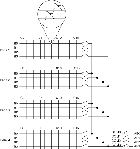
NI SCXI-1129 Hardware Diagram
The following figure shows the hardware diagram for the NI SCXI-1129.
 | Note Relay names are the same for every topology. |

The following table lists relay names for the NI SCXI-1129.
| Bank 1 Relays | Bank 2 Relays | Bank 3 Relays | Bank 4 Relays | Connection Relays | Analog Bus Relays |
|---|---|---|---|---|---|
| B1R0C0...B1R0C15 | B2R0C0...B2R0C15 | B3R0C0...B3R0C15 | B4R0C0...B4R0C15 | B1COM0...B1COM3 | AB0 |
| B1R1C0...B1R1C15 | B2R1C0...B2R1C15 | B3R1C0...B1R1C15 | B4R1C0...B4R1C15 | B2COM0...B2COM3 | AB1 |
| B1R2C0...B1R2C15 | B2R2C0...B2R2C15 | B3R2C0...B1R2C15 | B4R2C0...B4R2C15 | B3COM0...B3COM3 | AB2 |
| B1R3C0...B1R3C15 | B2R3C0...B2R3C15 | B3R3C0...B1R3C15 | B4R3C0...B4R3C15 | B4COM0...B4COM3 | AB3 |