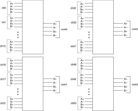
NI SCXI-1130 4-Wire Quad 16×1 Multiplexer Topology
Use the NI SCXI-1377 terminal block with the NI SCXI-1130 as a 4-wire quad 16×1 multiplexer. The following figure represents the NI SCXI-1130 in the 4-wire quad 16×1 multiplexer topology.

Making a Connection
In 4-wire mode, channel terminals CH 00 through CH 15 each have four leads that route in parallel to the OUT0, OUT1, OUT4, and OUT5 screw terminals on the NI SCXI-1377. OUT0, OUT1, OUT4, and OUT5 are addressed collectively as com0 in software. The other three banks follow a similar routing scheme.
Both the scanning command, ch2->com0;, and the immediate operation niSwitch Connect Channels VI or the niSwitch_Connect function with parameters ch2 and com0, result in the following connections:
signal connected to CH 02 is routed to OUT0
signal connected to CH 18 is routed to OUT1
signal connected to CH 66 is routed to OUT4
signal connected to CH 82 is routed to OUT5
Signal Connections
Refer to the Signal Connections section for the NI SCXI-1130 front connector pinout and NI SCXI-1377 terminal mapping.