NI PXI-2584 Interleaved Multiplexer (User-Implemented)
You can use the NI PXI-2584 independent topology to create a 2-wire 11×1 multiplexer. The independent topology interleaves the two multiplexer banks of the NI PXI-2584 to create one interleaved multiplexer. Interleaved multiplexing is useful for measuring stacked signals such as battery stacks where each channel shares a connection with the channels before and after it. By sharing connections you can nearly double the channel count while still maintaining 2-wire (differential) measurements.
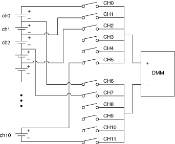
A representation of an interleaved multiplexer is shown in the following figure. The channels of the interleaved multiplexer are shown on the left of the figure.

 |
Note Signals connected to odd channels are measured in reverse polarity. |
 |
Note In multiple module operations, a straddled channel—an additional channel composed of the last channel of the first device (ch11) and the first channel of the second device (ch0)—is created between the two devices. |
Use the Independent topology for both scanning and immediate operation of the NI PXI-2584 when using it as a 2-wire 11×1 interleaved multiplexer.
Single Module Scanning
In single module scanning, to measure signals as shown in the preceding figure, complete the following steps:- Close CH0, and CH6. The DMM measures the signal between CH0 and CH6.
- Open CH0, and close CH1 (CH6 remains closed). The DMM measures the signal between CH1 and CH6, in reverse polarity.
- Open CH6, and close CH7 (CH1 remains closed). The DMM measures the signal between CH1 and CH7.
- Open CH1, and close CH2 (CH7 remains closed). The DMM measures the signal between CH2 and CH7, in reverse polarity.
- Continue this pattern for the rest of the channels.
- Open CH10, and close CH11 (CH5 remains closed). The DMM measures the signal between CH5 and CH11.
Refer to the following example for scan list syntax.
/Dev1/ch0->com0 & ch6->com1; ~ch0->com0 && ch1->com0; ~ch6->com1 && ch7->com1;...~ch10->com1 && ch11->com1; ~ch5->com0 & ~ch11->com1 &&
 |
Note When calling the niSwitch Configure Scan List VI or the niSwitch_ConfigureScanList function, select No Action for the scan mode parameter. |
Refer to the NI-SWITCH or the NI-DAQmx programming example for more information about single module scanning with the NI PXI-2584.
Multiple Module Scanning
In multiple module scanning, to measure signals on multiple devices, including the straddled channel signal, as shown in the following figure, complete the following steps:
- Follow the steps in single module scanning to measure the signals on the first device.
- Open CH5 on Dev1, and close CH0 on Dev2 (CH11 on Dev1 remains closed). The DMM measures the signal between CH11 on Dev1 and CH0 on Dev2 in reverse polarity.
- Open CH11 on Dev1, and close CH6 on Dev2 (CH0 on Dev2 remains closed) The DMM measures the signal between CH0 on Dev2 and CH6 on Dev2.
- Open CH0 on Dev2, and close CH1 on Dev2 (CH6 on Dev2 remains closed) The DMM measures the signal between CH1 on Dev2 and CH6 on Dev2 in reverse polarity.
- Open CH6 on Dev2, and close CH7 on Dev2 (CH1 on Dev2 remains closed) The DMM measures the signal between CH2 on Dev2 and CH7 on Dev2.
- Continue this pattern for the rest of the channels.
- Open CH10 on Dev2, and close CH11 on Dev2 (CH5 on Dev2 remains closed). The DMM measures the signal between CH5 on Dev2 and CH11 on Dev2.
Refer to the following example for scan list syntax.
/Dev1/ch0->com0 & ch6->com1; ~ch0->com0 && ch1->com0;...~ch5->com0 && /Dev2/ch0->com0; /Dev1/~ch11->com1 && /Dev2/ch6->com1; ~ch0->com0 && ch1->com0;...~ch10->com1 && ch11->com1; ~ch5->com0 & ~ch11->com1 &&
 |
Note When calling the niSwitch Configure Scan List VI or the niSwitch_ConfigureScanList function, select No Action for the scan mode parameter. |
Multiple module scanning with the NI PXI-2584 is supported only in NI-DAQmx. Refer to the NI-DAQmx programming example for more information about multiple module scanning with the NI PXI-2584.
Pinout
The following figure and table identify the pins for the NI PXI-2584 when used as a 2-wire 11×1 interleaved multiplexer.

| Interleaved Channel | Pin Name | |
|---|---|---|
| + | – | |
| ch0 | CH0 | CH6 |
| ch1 | CH6 | CH1 |
| ch2 | CH1 | CH7 |
| ch3 | CH7 | CH2 |
| ch4 | CH2 | CH8 |
| ch5 | CH8 | CH3 |
| ch6 | CH3 | CH9 |
| ch7 | CH9 | CH4 |
| ch8 | CH4 | CH10 |
| ch9 | CH10 | CH5 |
| ch10 | CH5 | CH11 |