Scanning NI Switches with NI Digital Multimeters
Several factors must be considered when you are scanning NI switches with NI digital multimeters (DMMs), including switch capabilities, chassis capabilities, and scanning mode. Depending on the hardware setup, multiple module scanning is only possible if single module scanning is possible. Single module scanning capabilities do not necessarily ensure that a multiple module scanning operation is possible. The following table lists the trigger inputs and outputs for all NI switches.
Trigger Options for National Instruments Switches
| Switch | INPUT Trigger Input | Output Trigger Output |
|---|---|---|
| SCXI-1127 SCXI-1128 | SCXI trig 0, Front, Rear | SCXI trig 2, Front |
| SCXI-1129 | all SCXI trig, Front, Rear | all SCXI trig, Front |
| SCXI-1130 SCXI-1166 SCXI-1167 SCXI-1193 | all SCXI trig, Front, Rear | |
| SCXI-1169 SCXI-1175 SCXI-1194 SCXI-1195 | all SCXI trig, Rear | |
| PXI-2501 PXI-2503 PXI-2529 PXI-2530 PXI-2566 PXI-2567 PXI-2593 | all PXI trig, Front | |
| PXI-2527 PXI-2532 PXI-2545 PXI-2546 PXI-2547 PXI-2548 PXI-2549 PXI-2554 PXI-2555 PXI-2556 PXI-2557 PXI-2558 PXI-2559 PXI-2564 PXI-2565 PXI-2568 PXI-2569 PXI-2570 PXI-2575 PXI-2576 PXI-2584 PXI-2585 PXI-2586 PXI-2590 PXI-2591 PXI-2594 PXI-2595 PXI-2596 PXI-2597 PXI-2598 PXI-2599 | all PXI trig | |
where
SCXI trig refers to SCXI trigger lines 0-7
PXI trig refers to PXI trigger lines 0-7
Rear refers to the rear connector
Front refers to the front panel or terminal block
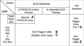
You can categorize different DMM/switch systems according to the DMM, the switch and the cable used. The following figure represents each possible system with a letter.
DMM/Switch System Options

The systems are classified as follows:
- System A—The DMM controls and triggers the SCXI switch using the internal PXI/SCXI lines of a PXI/SCXI combo chassis. The DMM is placed in the rightmost PXI slot of a combo chassis.
- System B—The DMM does not control the SCXI switch but triggers it using the AUX trigger cable. The SCXI switch is controlled by another device.
- System C—The DMM controls and triggers the SCXI switch using the SH9MD-AUX cable.
- System D—The DMM triggers the PXI switch using PXI trigger lines. PXI-4060 uses only PXI trigger lines 0 to 6. PXI-4070 uses PXI trigger lines 0 to 7.
- System E—A PXI or PCI DMM triggers the PXI switch using the AUX trigger cable.
The following table shows the scanning capabilities for every NI switch. The number after S or H indicates the setup number. For example, if you want to perform a synchronous scan with multiple SCXI-1130 modules using an AUX trigger cable, refer to setup 6. If you want to do handshaking with multiple PXI-2529 using PXI trigger lines, refer to setup 3. The links in the table direct you to Multiple Module Scanning setups. For single module setups, refer to Single Module Scanning.
Scanning Capabilities for National Instruments Switches
| Switches | System A PXI/SCXI Internal Lines |
System B AUX Trigger Cable |
System C SH9MD-AUX Cable |
System D PXI Trigger Lines |
System E AUX Trigger Cable |
|---|---|---|---|---|---|
| SCXI-1127/1128 | S7 | S6, H9 | S5 | ||
| SCXI-1129 | S7, H*10 | S6, H9 | S5 | ||
| SCXI-1130/1166/1167/1193/1194/1195 | S7, H*10 | S6, H9 | S5, H*8 | ||
| PXI-2501/2503/2527/2529/2530/2545/2546/2547/2548/2549/2554/2555/2556/2557/2558/2559/2566/2567/2576/2584/2593/2594/2595/2596/2597/2598/2599 | S1, H2 | S2, H4 | |||
| PXI-2532/2565/2568/2569/2570/2575/2590/2591 | S1, H2 | ||||
| SCXI-1160/1161/1163R/1190/1191/1192 | Scanning is not supported | ||||
| where S is synchronous scanning and H is handshaking H* indicates that handshaking is supported only with an NI 407x | |||||
As an alternative to synchronous scanning and handshaking VIs in NI-SWITCH, NI-DMM includes the NI-DMM/Switch Express VI. You can use the NI-DMM/Switch Express VI to configure and acquire a signal using NI-DMM with National Instruments digital multimeters (DMMs) and PXI or SCXI multiplexer switch modules. Refer to the NI Digital Multimeters Help at ni.com/manuals for more information about the NI-DMM/Switch Express VI.