NI SCXI-1129 2-Wire Dual 4×32 Matrix Topology
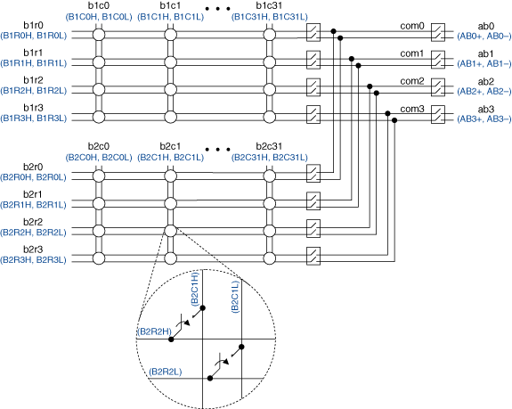
The NI SCXI-1339 terminal block provides connections to the NI SCXI-1129 in the 2-wire dual 4×32 matrix topology. The following figure represents the NI SCXI-1129 in the 2-wire dual 4×32 matrix topology.
 |
 |
Making a Connection
The SCXI-1129 in this topology contains two banks of 4×32 matrices. You can only connect rows and columns to rows and columns in the same bank.
For example, you can connect b1r1 to b1c0; however, you cannot connect b1r1 directly to b2c1 in this topology. When connecting signals for b1r1, connect them to B1R1H and B1R1L in the terminal block. When connecting signals for b1c0, you would connect them to B1C0H and B1C0L in the terminal block.
Notice you can connect to the high-voltage analog bus (HVAB) for routing signals to the back of the switch module.
You can connect the channels of the NI SCXI-1129 using the niSwitch Connect Channels VI or the niSwitch_Connect function. For example, to connect bank 1 row 1 to bank 1 column 1, call the niSwitch Connect Channels VI or the niSwitch_Connect function with the channel 1 parameter set to b1r1 and the channel 2 parameter set to b1c1.
When scanning the NI SCXI-1129, a typical scan list entry could be b1r1->b1c1;. This entry routes the signal connected to bank 1 row 1 to bank 1 column 1.
Bank Connection Diagram

Terminal Block Connections
The SCXI-1339 terminal block creates the following connections to operate the NI SCXI-1129 as a 2-wire dual 4×32 matrix. Refer to the Pinout section below for pin locations.
| Connection | Pins |
|---|---|
| 1 | b1r0+ to b2r0+ |
| 2 | b1r0- to b2r0- |
| 3 | b1r1+ to b2r1+ |
| 4 | b1r1- to b2r1- |
| 5 | b1r2+ to b2r2+ |
| 6 | b1r2- to b2r2- |
| 7 | b1r3+ to b2r3+ |
| 8 | b1r3- to b2r3- |
| 9 | b3r0+ to b4r0+ |
| 10 | b3r0- to b4r0- |
| 11 | b3r1+ to b4r1+ |
| 12 | b3r1- to b4r1- |
| 13 | b3r2+ to b4r2+ |
| 14 | b3r2- to b4r2- |
| 15 | b3r3+ to b4r3+ |
| 16 | b3r3- to b4r3- |
Pinout
The following figure identifies the pins for the NI SCXI-1129.
