NI SCXI-1127/1128 2-Wire 32×1 Multiplexer Topology
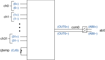
When using the NI SCXI-1127/1128 as a 2-wire 32×1 multiplexer, connect your signals using the NI SCXI-1331 terminal block. In this topology, use the screw terminal labeled 2W inside the NI SCXI-1331 terminal block. The following figure represents the NI SCXI-1127/1128 in the 2-wire 32×1 multiplexer topology.
 |
 |
Making a Connection
In 2-wire mode, all signals have two differential leads and connect to the NI SCXI-1331 on X+ and X-. Each signal pair is routed through the NI SCXI-1127/1128 and is available on OUT0+ and OUT0- screw terminals on the NI SCXI-1331 terminal block. You can further route both signals, OUT0+ and OUT0-, to high-voltage analog bus AB0+ and AB0-, respectively.
During scanning, a typical scan list entry is ch2->com0;. This entry routes the signal connected to 2+ and 2- to OUT0+ and OUT0- respectively. By default, this scan list entry will also route OUT0+ and OUT0- to AB0+ and AB0-.
When using the niSwitch Connect Channels VI or the niSwitch_Connect function with ch2 and com0 during immediate operations, the signal connected to 2+ and 2- are routed to OUT0+ and OUT0- respectively. To route OUT0+ and OUT0- to AB0+ and AB0-, use the niSwitch Connect Channels VI or the niSwitch_Connect function with com0 and ab0.
Pinout
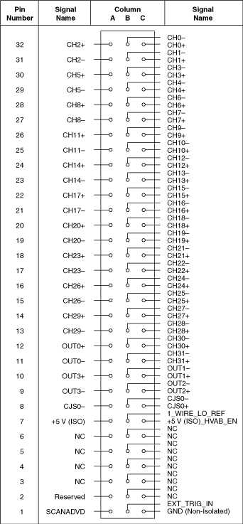
The following figure identifies the pins for the NI SCXI-1127/1128 in the 2-wire 32×1 multiplexer topology.
