NI PXI-2501/2503 2-Wire 4×6 Matrix Topology
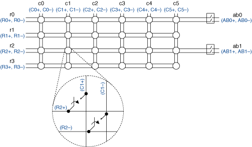
When using the NI PXI-2501/2503 as a 2-wire 4×6 matrix, connect your signals using the NI TB-2606 terminal block. The following figure is a representation of the NI PXI-2501/2503 in this mode.
 |
 |
Making a Connection
In this topology, connect your positive and negative leads to Cx± or Rx± inside the NI TB-2606 terminal block.
During immediate operations when you use the niSwitch Connect Channels VI or the niSwitch_Connect function with c0 and r0, the
signal connected to C0 ± is routed to R0 ±. To route R0 ± to AB0 ±, use the niSwitch Connect Channels VI or the niSwitch_Connect function with r0 and ab0.
Terminal Block Connections
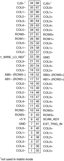
The NI TB-2606 terminal block creates the following connections to operate the NI PXI-2501/2503 as a 2-wire 4×6 matrix topology. Refer to the pinout for pin locations.
The following table lists the pins the NI TB-2606 shorts and the column connections created.
| Connections | Pins | Connections | Pins | Connections | Pins |
|---|---|---|---|---|---|
| C0+ | 67,59,50,40 | C2+ | 65,57,48,38 | C4+ | 63,54,46,36 |
| C0- | 33,25,16,6 | C2- | 31,23,14,4 | C4- | 29,20,12,2 |
| C1+ | 66,58,49,39 | C3+ | 64,55,47,37 | C5+ | 62,53,45,35 |
| C1- | 32,24,15,5 | C3- | 30,21,13,3 | C5- | 28,19,11,1 |
The following table lists the pins and their associated row connection.
| Connections | Pins | Connections | Pins | Connections | Pins | Connections | Pins |
|---|---|---|---|---|---|---|---|
| R0+ | 61 | R1+ | 60 | R2+ | 44 | R3+ | 43 |
| R0- | 27 | R1- | 26 | R2- | 10 | R3- | 9 |
Pinout
The following figure identifies the pins for the NI PXI-2501/2503 in the 2-wire 4×6 matrix topology.
