Bandwidth and Insertion Loss
Signal bandwidth is the useful range of signal frequencies for a switch. NI switch modules are specified for frequencies as low as DC, so bandwidth is specified as the maximum recommended signal frequency. In many cases, bandwidth is the highest signal frequency that the switch can maintain <3 dB of insertion loss. Some RF modules specify bandwidths based on reflections (VSWR) instead of insertion loss.
Insertion Loss
As a high-frequency signal traverses through a switch module, it is attenuated by series resistance, dielectric absorption, and by reflections from impedance mismatches. This attenuation is called insertion loss. The amount of signal remaining at the output of the switch module is represented as a ratio to the input signal in decibels (dB):
Transmitted signal (dB) = 10 log(Pout/Pin)
where Pout is the output power level, and Pin is the input power level.
This ratio can also be expressed in terms of signal voltage:
Transmitted signal (dB) = 20 log(Vout/Vin)
Because the switch attenuates the signal, output magnitude is less than input magnitude, and the transmitted signal ratio is always <0 dB.
By convention, insertion loss is the ratio of input signal to the output signal, in decibels (dB):
Insertion loss (dB) = 10 log(Pin/Pout) = -10 log(Pout/Pin)
Insertion loss (dB) = 20 log(Vin/Vout) = -20 log(Vout/Vin)
Output magnitude is less than input magnitude, so insertion loss is >0 dB.
The contributing factors of series resistance, dielectric loss, and mismatch reflections are frequency dependent and generally result in insertion loss rising with signal frequency.
The following figures illustrate single-ended and differential measurements, respectively.
 |
 |
Bandwidth and Square Waves
If a signal is purely sinusoidal, the bandwidth/insertion loss rating of a switch module can be directly applied. For signals that have multiple frequency components, like a square wave, the rating may be difficult to apply.
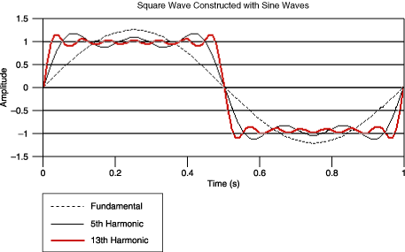
A square wave can be represented using a natural harmonic series, where only the odd harmonics are used. The frequency components that make up an ideal square wave are infinite.
Square wave (t) = (4/ )[sin
)[sin  t + (1/3)sin 3
 t + (1/5)sin 5
 t + …]
where  is frequency in radians per second
A square wave may have a fundamental frequency below the rated bandwidth. However, harmonics above the rating may be attenuated by increasing insertion loss.
For example, consider a 2 V peak-to-peak square wave. The square wave can be approximated by the summation of multiple harmonic sine waves. Three harmonics are shown in the following figure: the fundamental frequency (or first harmonic), the fifth, and the 13th harmonic.
 |
If the frequency content of a square wave is known, the required switch bandwidth can be determined based on the highest harmonic to be passed with minimal distortion.
If the frequency content is unknown, the –3 dB point can be approximated using the rise time of the harmonic to be preserved. The rise time is related to the –3 dB point bandwidth by the following approximation:
3 dB bandwidth (Hz) ≈ 0.35/τr
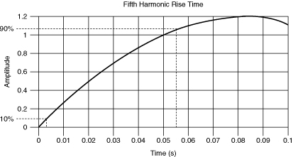
where τ is the rise time from 10% to 90% of the signal amplitude.
The following figure shows this approximation applied to the fifth harmonic of the square wave from the previous example:
 |
where τ = 0.0515 s
3 dB bandwidth = 6.79 Hz
To preserve the rise time of the signal, a switch with an insertion loss of 3 dB at 6.79 Hz minimum should be chosen.
For a square wave, once the fifth or seventh harmonic is reached, the change in the rise time is minimal. In the previous example, a switch with an insertion loss of 3 dB at 7 Hz will be sufficient to pass as a 1 Hz square wave.
 |
Tip For square wave signals, select a switch with a –3 dB point at a frequency seven times the fundamental frequency of the square wave. If less attenuation is desired, the –3 dB point should be a higher frequency. |