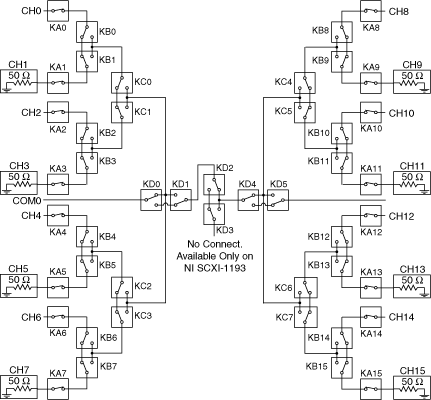
NI PXI-2593 8×1 Terminated Multiplexer Topology
The following figure represents the NI PXI-2593 8×1 terminated multiplexer topology.
 |
 |
The following figure shows the reset position of the NI PXI-2593 in the 8×1 terminated multiplexer topology.

For proper termination, connect an external terminator, such as the NI 50 Ω MCX terminator (778831-01), to every odd channel. Any input channel not connected to the COM is routed back to its associated termination channel.
The NI PXI-2593 in this topology contains 8 channels connected to a common channel. These channels are referred to as ch<0..14>, and the common channel is referred to as com0. You can connect any even input channel to com0 in this topology.
Making a Connection
You can connect the channels of the NI PXI-2593 using the niSwitch Connect Channels VI or the niSwitch_Connect function. For example, to connect channel 14 to common 0, call the niSwitch Connect Channels VI or the niSwitch_Connect function with the channel 1 parameter set to ch14 and the channel 2 parameter set to com0.
When scanning the NI PXI-2593, a typical scan list entry could be ch2->com0;. This entry routes signal connected to ch2 to com0.