NI PXI-2501/2503 1-Wire 48×1 Multiplexer Topology
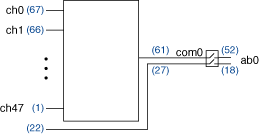
When using the NI PXI-2501/2503 as a 1-wire 48×1 multiplexer, connect your signals using the NI TB-2605 terminal block. The following figure is a representation of the NI PXI-2501/2503 in this mode.
 |
 |
Making a Connection
In 1-wire mode, all signals connected to the NI TB-2605 have the same reference. Connect this reference to screw terminal 27 on the NI TB-2605.
During scanning, a typical scan list entry is ch2->com0;. This entry routes the signal connected to ch2 (screw terminal 65) to COM0 (screw terminal 27).
During immediate operations when using the niSwitch Connect Channels VI or the niSwitch_Connect function with ch2 and com0, the signal connected to ch2 (screw terminal 65) is routed to COM0 (screw terminal 27). To route the signals to ABO, use the niSwitch Connect Channels VI or the niSwitch_Connect function with com0 and ab0.
Pinout
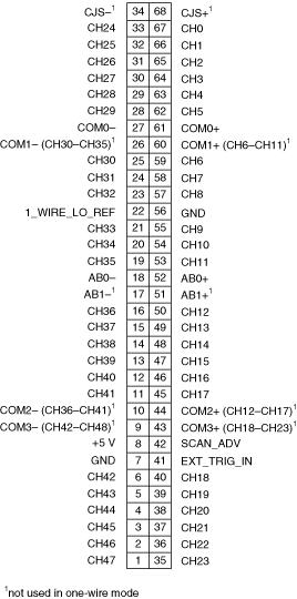
The following figure identifies the pins for the NI PXI-2501/2503 in the 1-wire 48×1 multiplexer topology.
