Data Marker Events
The Data Marker events allow you to export any one of the 16 waveform data bits to any valid destination on the device. Up to four of the 16 waveform data bits can be exported at one time. Refer to Features Supported to determine if your device supports data marker events.
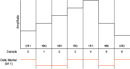
The level of a Data Marker event changes at the time that a specific data bit toggles in the waveform data. If the waveform data bit toggles multiple times in a segment, the Data Marker event level changes each time. When the data bit level is high, the Data Marker event level is high. You can invert this relationship by setting the Data Marker Event Level Polarity property or the NIFGEN_ATTR_DATA_MARKER_EVENT_LEVEL_POLARITY attribute.
The following figure shows the exported data marker event shifting between low and high as the specified data bit toggles.

NI-FGEN compensates for the factors that affect the delays in the digital and analog paths in assuring that the Data Marker event appears within one Sample clock of the waveform output.
Creating and Exporting Data Marker Events
To create and export a Data Marker event, complete the following steps:
- Specify a data bit number using the Data Marker Event Bit Number property or the NIFGEN_ATTR_DATA_MARKER_EVENT_DATA_BIT_NUMBER attribute.
- Set the output polarity of the data marker event using the Data Marker Event Level Polarity property or the NIFGEN_ATTR_DATA_MARKER_EVENT_LEVEL_POLARITY attribute.
- To export the data marker, use the niFgen Export Signal VI or the niFgen_ExportSignal function. To determine all possible signal routes for your device, refer to Signal Routing.

Note When exporting data markers, you must specify the signal identifier for the data marker using the of the niFgen Export Signal VI or the niFgen_ExportSignal function.
Data Markers as Trigger Outputs
A delay of at least 44 Sample clocks exists between the Start trigger and when the analog waveform generation on the output connector. Therefore, synchronizing the signal generator output signal to other devices with fast trigger response times is accomplished using the data marker event from the signal generator as the trigger source for the other device for more precise alignment to the generating waveform. You can do this using the RTSI bus, PXI trigger lines, SYNC OUT/PFI 0 and PFI 1 or PFI 4 and PFI 5. Refer to Exporting Signals for more information about routing signals off the device.
 |
Note Devices without a DDC connector do not support PFI <4..5>. |