Impedance Matching
When broadband signals are carried on transmission lines of any significant length, care must be taken that the transmission line is matched to its terminations. The source and load impedances should equal the characteristic impedance of the transmission line, as this minimizes signal reflections. The presence of impedance discontinuities or mismatches degrade the amplitude and phase accuracy, as well as the temporal fidelity, of waveforms generated with a signal generator.
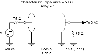
One of the most common mismatch errors encountered in such measurements is shown in the following figure:

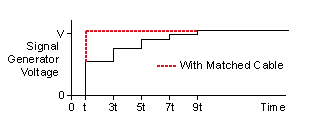
In this example, selectable source impedances are provided at the signal generator outputs to accommodate the most popular coaxial cable characteristic impedances: 50 Ω and 75 Ω. The following figure shows what happens when, as in this example, a coaxial cable of the wrong characteristic impedance (50 Ω) is used with 75 Ω source and load impedances:

The pulse encounters impedance mismatches at each end of
the cable, causing the pulse to be partially reflected. The reflected pulse traverses
the cable back and forth numerous times, diminishing at each end by the
reflection coefficient,  .
.

where
vr = reflected voltage
vi = incident voltage
zt = terminating impedance
z0 = characteristic impedance
The resulting voltage waveform is distorted by the asymptotic decay of the reflected pulse as shown, exaggerated for visual effect. Impedance discontinuities of smaller magnitude and/or duration have correspondingly smaller effects. Also displayed is the waveform that results when a cable of matched impedance (75 Ω) is used.
Mismatch Uncertainty
Impedance matching is also important for preserving the absolute delivered power from a device. The accuracy with which power can be delivered is limited by mismatch error. The mismatch error in a z0 system can be shown to be bounded by:

 L = load reflection coefficient
 G = generator reflection coefficient
The denominator term represents mismatch uncertainty, which is a fundamental limit to the power transfer accuracy that can be achieved across a mismatched junction.
Resistive Matching
Signal generators with low/high-source impedance can be matched with a resistor placed in series (shunt) such that the total source impedance (admittance) is matched to the cable characteristic impedance (admittance). Signal generators that are not capable of driving the cable impedance directly can be coupled through a matching L-pad. In this case, the signal generator sees an approximately 500 Ω load, while the source impedance presented to the cable is 50 Ω, as shown in the following figure:

High-frequency components and layout techniques should be used throughout to minimize parasitic effects.