NI 5412/5421/5422/5441/5442
Onboard Memory
NI 5412/5421/5422/5441/5442 signal generators use an onboard memory that is 16-bits wide. The minimum standard memory size for the NI 5412/5421/5422/5441/5442 is 8 Mbytes which translates to 8,338,608 usable bytes. With the minimum standard memory size, you can store very long waveforms on the device and obtain reliable waveform generation at full sample rate of 100 MS/s (or 200 MS/s for the NI 5422). The NI 5421/5422/5441/5442 also comes with higher memory options of 32 Mbytes, 256 Mbytes, and 512 Mbytes. The NI 5412 comes with higher memory options of 32 Mbytes and 256 Mbytes.
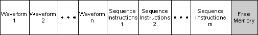
The onboard memory is a single large memory area that stores both waveforms and sequence instructions to generate the waveforms. The instructions for a complicated sequence can occupy a significant portion of memory. The architecture of the NI 5412/5421/5422/5441/5442 allows you to load multiple waveforms and multiple sequence instructions into the memory. The following diagram illustrates NI 5412/5421/5422/5441/5442 memory allocation. A number of waveforms are stored in the onboard memory ranging from 1 to n; there are also a number of sequence instructions ranging in number from 1 to m. The values of n and m depend on the waveform and instructions configured and are ultimately limited by the amount of memory.
The following tables list the types of information that are used to make up the instructions that are saved to memory. You can store the instructions for multiple sequences to the onboard memory ahead of time and generate them later, allowing for quick reconfiguration times between tests. There are two example sequences. The first table, Sequence 1, represents the instructions for a sequence containing a maximum number of segments k. The second table, Sequence m, is an example of a sequence containing 8 segments. Each sequence uses different waveforms that are downloaded to the onboard memory, as well as various looping and Marker placement options to construct each resulting waveform.
|
| |||||||||||||||||||||||||||||||||||||||||||||||||||||||||||||||||||||||||||||||||