Waveform Fundamentals
Filtering and Interpolation
All NI signal generators use a digital-to-analog converter (DAC) to generate the signals or waveforms that eventually appear at the output connector. These generated signals have a number of discrete voltage levels dependent on the number of bits in the DAC.
A digital waveform must be updated at least twice as fast as the bandwidth of the desired analog signal to be accurately generated (Shannon's Sampling Theorem). Even though the theoretical requirement for Sample clock, fs, is twice that of the signal bandwidth, fo, images are introduced in the output signal at |fo ± nfs|, as shown in the following figure.
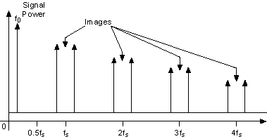
The images shown in the previous figure degrade the spectral purity of the signal, creating the need to filter these images out of the signal.
To create quality signals, all NI signal generators can lowpass filter the generated signal. A lowpass filter can smooth the raw DAC output. The filter removes high-frequency aliased components that are introduced through the digital generation of the signal. You can implement the lowpass filter through both analog and digital filters.
Designing an analog filter that rejects the images and yet gets maximum output bandwidth (0 to 0.43fs) is difficult and is represented by the curve Analog Filter 1 in the following figure. Analog Filter 2 represents a more practical filter. This filter is not as aggressive as Analog Filter 1. Analog Filter 2 does not filter out the images near fs, but it does reject all the others. Analog filters have trade-offs between the roll-off of the attenuation after the 3 dB point and the flatness of the attenuation before the 3 dB point.
Another aspect of the analog filter is group delay—the amount of time needed for a signal having finite time duration, such as a pulse, to pass through the analog filter. Ideally, in an analog filter with linear group delay, all frequencies present in the signal should have the same time delay so that the signal is not distorted.
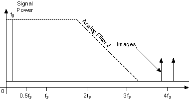
The third filter, Analog Filter 3, has a much higher 3 dB point than the first two analog filters. Because of the higher 3 dB point, the filter is very nearly flat in the passband (0 to 0.43fs). Analog Filter 3 does not filter the images produced at fs and 2fs at all, but this shortcoming can be alleviated with a digital interpolation filter.
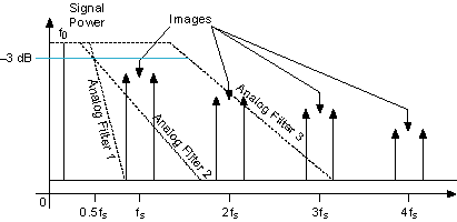
To ease the requirements of the analog filter and to get more output bandwidth, NI signal generators use a halfband digital filter to interpolate one, three, or seven samples between every two waveform samples at two times, four times, and eight times the sample frequency, fs. Also, the DAC operates at an effective sampling rate that is two times (2fs), four times (4fs) and eight times (8fs) the sample frequency—specifically, the rate at which the data is clocked from the memory into the DAC.
In the following figure, the two times interpolating filter is used and the effective sample rate of the DAC is 2fs. The images at fs ± fo are no longer an issue, and the images are now at |2fs ± fo|.
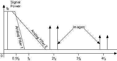
Now, Analog Filter 2 can easily filter out all the images due to the digital generation of the signal. This behavior is seen in the frequency domain representation in the previous figure and in the time domain representation in the following figure.
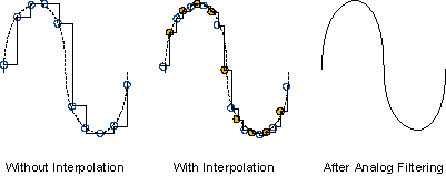
 |
Note The allowable range of interpolation factors is dependent on the NI signal generator being used. |
Using two times interpolation filtering with a DAC effective sample rate of 2fs eliminates images well and generates a good signal. However, increasing the interpolation filter to 4 further improves the output signal.
The following figure shows a signal image with four times interpolation, and the effective DAC sample rate at 4fs. The images are shifted up to 4fs, and well above the cutoff frequency of Analog Filter 3. This configuration eliminates the spectral images and has a filter that is maximally flat within the passband. This configuration approaches an ideal design in digitally generating spectrally pure waveforms.
To generate the most spectrally pure signals using the digital filter, you should use the highest interpolation factor that you can.