NI PXI-5404
Start Conditions
SINE Out
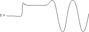
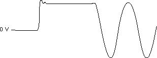
The sine waveform is configured by three parameters: frequency, amplitude, and phase. All the parameters are sent to the direct digital synthesis chip at the same time; however, because of delays within the chip, the phase and amplitude are set before the frequency. The result of these delay differences is a DC voltage at the SINE out before the sine signal appears. The duration of this DC signal is about 100 ns, and its level depends on the given phase and amplitude. You can see this start up condition for different phase settings in the following figures.

Sine Output Starting for Phase Set to 45 Degrees

Sine Output Starting for Phase Set to 90 Degrees
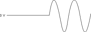
Because a phase of 0° or 180° corresponds to a starting amplitude of 0 V, you can use one of these two phase settings to eliminate this particular start up condition. Refer to the following figure for an example of a start phase of 0°.

Sine Output Starting for Phase Set to 0 Degrees
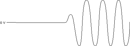
In addition, when generating higher frequencies, a runt pulse exists upon start-up. Refer to the following figure for an example of a runt pulse.

Runt Pulse on SINE Output When Starting at a High Frequency for Phase Equal to Zero
CLOCK Out
The start condition of the CLOCK out depends on the start phase of the SINE out. Therefore, a runt pulse may occur upon starting the clock. Refer to the following figure for an example of a runt pulse.

Runt Pulse on Start-up of CLOCK Output for Phase Equal to Zero
For certain phase settings, the runt pulse does not occur. To eliminate the runt pulse on the CLOCK out, experiment with the starting phase setting.
Also, because of the different output paths of the CLOCK out and SINE out, a fixed delay exists after the SINE out initiates until the CLOCK out initiates.