NI PXI/PCI-5411/5431
Master/Slave Operation
You can phase lock the NI 5411 to other devices or other NI 5411 signal generators in two different ways to synchronize multiple devices in a test system.
- NI PCI-5411/5431
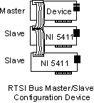
The following figure shows master/slave configurations for phase locking any NI signal generator with RTSI bus capability as the master.

To phase lock an NI 5411/5431 to this master, complete the following steps:
- Set the NI master device to send a 20 MHz signal over the RTSI bus on the RTSI Osc line. If this device is an NI 5411/5431, set the source for the RTSI clock line to device_clock for NI-FGEN and internal for LabVIEW.
- Set up the slave devices so that the RTSI clock line is the PLL reference source.
- Set the PLL reference frequency parameter to 20 MHz. The devices are now frequency locked to the master.
- To further phase lock the devices, set up the master to send the trigger signal on one of the RTSI trigger lines.
- Set up the slave devices to receive their trigger signal on the RTSI bus.
- Start the waveform generation on all the slaves.
- Start the waveform generation on the master.
The master triggers all the slaves that are phase and frequency locked to each other and the master.
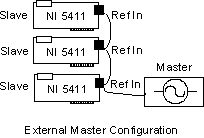
The following figure shows the master/slave configuration for phase locking an external device as the master.

To phase lock NI 5411 signal generators to this master, complete the following steps:
- Set the master device to send any valid Reference clock to the PLL reference input connector.
- Set up the slave devices with the I/O connector as the PLL reference source.
- Set the PLL reference frequency parameter to the clock frequency sent by the master. The devices are now frequency locked to the master.
- To further phase lock the devices, connect the trigger source to the trigger input of the 50-pin digital connectors of all the devices, and set up the slaves to receive the triggers on trigger input connector.
- Start the waveform generation on all the slaves.
- Activate the external trigger signal. All the slaves are triggered at the same time and are phase and frequency locked.
- NI PXI-5411/5431
To phase lock NI PXI-5411/5431 signal generators, complete the following steps:
- Set all the NI 5411/5431 signal generators to accept the 10 MHz Osc line on the PXI backplane as the PLL Reference clock signal.
- Set the PLL reference frequency to 10 MHz. The devices are now frequency locked to the backplane 10 MHz Osc line.
- Select the Sample clock source to internal divide-down mode, high-resolution mode, or external clocking mode. External clocking mode results in the best synchronization.
- To further phase lock the devices, set up the master to send the trigger signal on one of the PXI trigger lines.
- Set up the slaves to receive their trigger signal on the PXI trigger bus.
- Set up the master to send the device_SYNC signal on the PXI trigger line and the slaves to receive the device_SYNC signal on the same PXI trigger line.
- Start the waveform generation on all the slaves.
- Start the waveform generation on the master.
The master triggers all the slaves, which are phase and frequency locked to each other and the master.
 |
Note If two or more NI 5411 signal generators are running in Direct Digital Synthesis mode and are locked to each other using the same Reference clock, they are frequency locked, but the phase relationship is indeterminate. |
- NI PCI-5431 Video Generation
 |
Note When generating a video waveform, do not phase lock the NI 5431 if the Video Waveform Type property or the NIFGEN_ATTR_VIDEO_WAVEFORM-TYPE attribute is used to set the internal frequency of the device. For synchronized video generation, a master NI 5431, which is run with the Video Waveform Type property or the NIFGEN_ATTR_VIDEO_WAVEFORM_TYPE attribute set, provides a reference 20 MHz signal over the RTSI bus. The slaves run with the Video Waveform Type property or the NIFGEN_ATTR_VIDEO_WAVEFORM_TYPE attribute not set, phase locking to the external 20 MHz reference, thereby running at the correct clocking frequency. |
The following figure for master/slave configurations for phase locking shows an NI PCI-5431 as the master.

To phase lock an NI PCI-5431 to this master, perform the following steps:
- Set the NI 5431 (master) to send a 20 MHz signal over the RTSI bus on the RTSI Osc line. Set the source for the RTSI clock line to device_clock for NI-FGEN and internal for LabVIEW. Set the Video Waveform Type property or the NIFGEN_ATTR_VIDEO_WAVEFORM_TYPE attribute that is generating.
- Set up the slave devices so that the RTSI clock line is the PLL Reference source. Ensure that Video Waveform Type property or the NIFGEN_ATTR_VIDEO_WAVEFORM_TYPE attribute is not being set.

Note The Video Waveform Type property is set in the NI 5431 HL Setup Attributes VI. Remove this property node for all slave devices. - Set the PLL reference frequency parameter to 20 MHz. The devices are now frequency locked to the master.
- To further phase lock the devices, set up the master to send the trigger signal on one of the RTSI trigger lines.
- Set up the slave devices to receive the trigger signal on the RTSI bus.
- Start the waveform generation on all the slaves.
- Start the waveform generation on the master.
The master triggers all the slaves that are phase and frequency locked to each other and the master.
- NI PXI-5431 Video Generation
The NI PXI-5431 does not support synchronization through phase locking when the Video Waveform Type property or the NIFGEN_ATTR_VIDEO_WAVEFORM_TYPE attribute is set. However, PAL video generation is still possible by clocking the NI 5431 normally. To do generation or clocking, remove the property node that sets the Video Waveform Type in the NI 5431 HL Setup Attributes VI.
 |
Note If two or more NI 5411/5431 signal generators are running in Arbitrary Waveform Generation mode and are locked to each other using the same Reference clock, you see a maximum phase difference of one Sample clock on the locked devices when they are triggered at the same time. |