NI PXI/PCI-5401
Analog Output
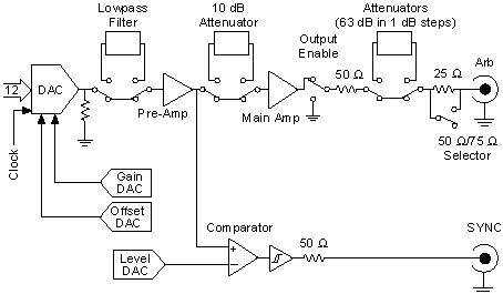
Analog waveforms generate as follows:
- The 12-bit digital waveform data is fed to a high-speed DAC.
- A lowpass filter filters the DAC output.
- This filtered signal is amplified before it goes to a 10 dB attenuator.

Note The DAC output can be fine-tuned for gain and offset. Since the offset is adjusted before the main attenuators and amplifier, the offset is referred to as pre-attenuation offset. The fine-tuning of gain and offset is performed by separate DACs. - The output from the 10 dB attenuator then goes to the main amplifier, which can provide up to ±5 V levels into 50 Ω. An output relay can switch between ground level and the main amplifier.
- The output of this relay goes to a series of passive attenuators.
- The output of the attenuators goes through a selectable output impedance of 50 Ω or 75 Ω to the I/O connector.
The following figure shows the essential block diagram of analog waveform generation.

The following figure shows the timing relationships of the trigger input and waveform output. td1 is the pulse width on the trigger signal. td2 is the time delay from trigger to output on ARB output.
