NI 5421/5422/5441
DIGITAL DATA & CONTROL Connector
The DIGITAL DATA & CONTROL (DDC) front panel connector is a 68-pin female VHDCI connector that contains the 16-bit LVDS digital pattern output. The DDC connector is an optional feature for the NI 5421/5422/5441.
NI 5421/5422/5441 DIGITAL DATA & CONTROL Pin Assignments
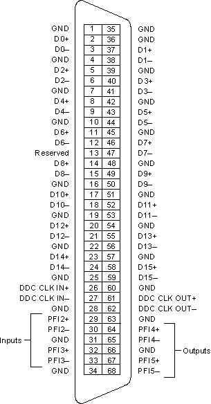
The following figure shows the NI 5421/5422/5441 DDC 68-pin connector.

The following table lists the pin names and signal descriptions used for the NI 5421/5422/5441 DDC connector. All lines are at standard LVDS levels.
| Signal Name | Type | Description |
|---|---|---|
| D<0..15> | Output | Digital pattern outputs–The 16-bit digital representation of the analog waveform is available on these output pins as digital pattern outputs. This data is available directly from the memory after several Sample clock pipeline delays. The digital pattern outputs are standard LVDS output levels. All data bits change on the falling edge of the DDC CLK OUT. |
| DDC CLK IN | Input | Digital Data Clock In–These lines are used as a source for an external Sample clock. You can feed a LVDS level clock to this line with a maximum frequency of the signal generator. |
| DDC CLK OUT | Output | Digital Data Clock Out–The Sample clock is always routed to the DDC CLK OUT line of the DDC front panel connector when the digital pattern is enabled. |
| Ground | – |
Digital ground |
| PFI<2..3> (Inputs) | Input | PFI<2:3>–These PFI lines can accept a trigger from an external source that can start or step through waveform generation. You can select this functionality on the NI 5421/5422/5441 through the software. Refer to Trigger Sources for more information. |
| PFI<4:5> | Output | PFI<4..5>–These PFI lines can route out a signal from the following sources:
|
| Reserved | – |
Reserved for future use. Do not connect signals to this line. |
| Refer to the NI 5421, NI 5422, or the NI 5441 specifications for information about acceptable input signal characteristics to connect to the DDC lines, as well as the output signal characteristics. | ||
You must enable the DDC connector before the signals in this table are available for use, refer to niFgen Configure Digital Patterning VI or niFgen_EnableDigitalPatterning and niFgen_DisableDigitalPatterning function topics for more information.