How the NI Video Software Toolkit Filters Video Components
The NI Video Software Toolkit has several ways to filter different video components while computing a video signal. The video formats PAL, NTSC, and SECAM require some of the filters, while other filters are optional. Three filtering modes exist:
- One or more of the predefined FIR filters
- One or more of the predefined IIR filters
- One or more user-defined FIR or IIR filters. Refer to the Advanced Color Bars from ITS with Custom Filters example.
Predefined filters do not have a group delay across the entire frequency range. In other words, phase error and delay do not exist between any part of the different signal components, whether these components are filtered or not.
 |
Note The IIR filters are not classical-type IIR filters but rather an advanced version of the IIR filtering with symmetrical impulse response, that is, zero group delay error. |
The key difference between an FIR and an IIR filter is whether the impulse response is finite (FIR) or infinite (IIR). FIR filtering is faster in computation than IIR filtering and often has a step response with less overshoot than the equivalent IIR filter. On the other hand, the frequency response of the FIR filters is not as sharp as the corresponding IIR filter.
The use of the FIR or IIR filter type depends on the application. If frequency attenuation is important, the IIR filters are recommended. If fast calculation time is a higher priority, then the FIR filters may be a better choice. If you do not specify anything, the video toolkit software uses default filters that fulfill the different requirements of the video standards.
The default filters are as follows:
- For NTSC:
- Y (luminance component): No filter
- Q (first chroma component): 0.4 MHz IIR filter
- I (second chroma component): 1.3 MHz FIR filter
- Entire composite signal: No filter
- For PAL or SECAM:
- Y (luminance component): No filter
- U (first chroma component): 1.3 MHz FIR filter
- V (second chroma component): 1.3 MHz FIR filter
- Entire composite signal: No filter
The following table lists the filter specifications.
| Filter Cut-Off | Designed for Filtering | Filter Type | Attenuation at Cut-Off | Stop-Band Frequency | Attenuation in Stop Band |
|---|---|---|---|---|---|
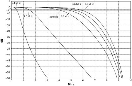
| 0.4 MHz | Q component | IIR only | < 2 dB | 0.6 MHz | > 6 dB |
| 1.3 MHz | I/U/V component | FIR/IIR | < 2 dB | 3.6 MHz | > 20 dB |
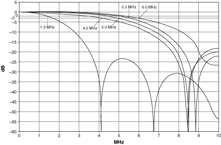
| 4.2 MHz | M-NTSC signal | FIR/IIR | 3 dB | Refer to following figures | Refer to following figures |
| 5.0 MHz | B/G-PAL signal | FIR/IIR | 3 dB | Refer to following figures | Refer to following figures |
| 5.5 MHz | I-PAL signal | FIR/IIR | 3 dB | Refer to following figures | Refer to following figures |
| 6.0 MHz | D-PAL signal | FIR/IIR | 3 dB | Refer to following figures | Refer to following figures |
The following figures show the frequency response for all the predefined FIR and IIR video filters.

Frequency Response for the Predefined FIR Filters
