Marker Events
A marker is an event that the device generates in relation to a waveform that is generated. The event is configured to occur at the time that a specific location or sample n in the waveform generates on the CH 0 connector. If the waveform loops multiple times in a segment, the marker generates each time the waveform loops. The following figure shows a pulse that represents a waveform sample n that is one Sample clock in width of a waveform being generated on the CH 0 connector. The second pulse, the Marker event, represents the pulse that generates when the corresponding waveform sample n outputs at the CH 0 connector. Refer to Features Supported to determine if your device supports markers.
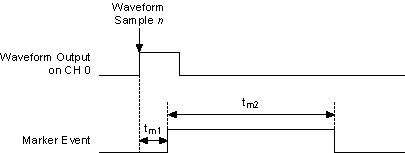
tm1 represents the delay in time of the Marker event generated relative to the configured waveform sample n being generated.
tm2 represents the Marker event pulse width in time.
NI-FGEN takes into account the factors that affect the delays in the Digital and Analog paths in assuring that the Marker event appears within one Sample clock of the waveform output. Therefore, tm1 is less than one Sample clock period.
The Marker event pulse width, tm2, is at least 150 ns and can be significantly longer than 150 ns for slower Sample clocks. You can configure the pulse width by setting the Marker Event Pulse Width property or the NIFGEN_ATTR_MARKER_EVENT_PULSE_WIDTH attribute. Instruments commonly have a minimum pulse width specification for a trigger to be registered, and trigger pulses of smaller width are ignored. The signal generator ensures that a minimum pulse width exists on the Marker event by using a pulse stretching circuit. A Sample clock rate of 100 MS/s has a period of 10 ns, requiring the pulse to be lengthened for many devices to register the marker as a good trigger pulse. Refer to the module specifications for the timing specifications.
Creating Markers
You can specify a marker and its location by setting an offset location value (in number of samples) from the start of the waveform. If the offset is out of range of the number of samples in that segment, NI-FGEN returns an error. There are two rules for marker placement:
- A marker can be specified only at offsets that are multiples of four samples (or two complex samples).
- A marker must be placed at least four samples from the end of the waveform. In Burst trigger mode, a marker must be placed at least eight samples from the end of the waveform.
For example, for a waveform containing 100 samples, a marker at an offset of 0 or 4 is valid, but a marker at an offset of 3 is invalid. In addition, a marker at an offset of 97 or 100 is always invalid, while a marker at an offset of 96 is valid for all trigger modes except Burst. The marker can be placed at an offset of 92 for all trigger modes.
To create a marker in Arbitrary Waveform Mode, set the Arbitrary Waveform Marker Position property or the NIFGEN_ATTR_ARB_MARKER_POSITION attribute. Then use the niFgen Export Signal VI or the niFgen_ExportSignal function to export the marker signal.
To create a marker in Arbitrary Sequence Mode, refer to the Marker Location Array parameter of the niFgen Create Advanced Arb Sequence VI or the niFgen_CreateAdvancedArbSequence function. Then use the niFgen Export Signal VI or the niFgen_ExportSignal function to export the marker signal.
In script mode, you can create up to four markers for each waveform. To create markers in script mode, refer to the NI Script Editor Help. Then use the niFgen Export Signal VI or the niFgen_ExportSignal function to export the marker signal.
 |
Note When exporting markers in script mode, you must specify the marker using the Signal Identifier parameter of the niFgen Export Signal VI or the niFgen_ExportSignal function. |
Markers as Trigger Outputs
A delay of at least 44 Sample clocks exists between the Start trigger and the analog waveform generation on the output connector. Therefore, synchronizing the signal generator output signal to other devices with fast trigger response times is accomplished using the Marker event from the signal generator as the trigger source for the other device for more precise alignment to the generating waveform. You can do this using the RTSI bus, PXI trigger lines, SYNC OUT/PFI 0 and PFI 1 or PFI 4 and PFI 5. Refer to Exporting Signals for more information about routing signals off the device.
|
Note Devices without a DDC connector do not support PFI<4..5>. |