NI 5442
Analog Output Path
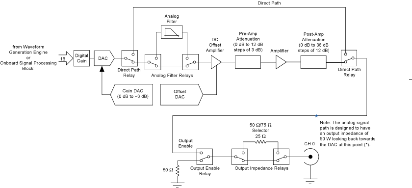
The following figure shows the NI 5442 Analog Output path.
;)
NI 5442 Analog waveforms are generated as follows:
- The 16-bit digital waveform data from the waveform generation engine or OSP is passed to a digital gain circuit and then a high-speed DAC. This DAC also implements a portion of the Analog Output path attenuation with a range of 0 to 3 dB. Refer to the NI 5442 specifications for the exact resolution. You can adjust the amount of attenuation by configuring the Arbitrary Waveform Gain or Amplitude properties or the NIFGEN_ATTR_ARB_GAIN or NIFGEN_ATTR_FUNC_AMPLITUDE attributes. NI-FGEN calculates and sets the correct amount of attenuation required, corresponding to the gain setting.
-
Following the DAC, the signal can take one of two paths: the Direct path or the Main path. NI-FGEN selects the Main path by default. To select the Direct path, refer to the Analog Path property or the NIFGEN_ATTR_ANALOG_PATH attribute.
- The Direct path bypasses the analog filter, the attenuation sections, and the amplifiers. Taking the amplifiers out of the signal path yields an output signal with the lowest distortion and a flat frequency response. Use the Direct path for communication signals. The Direct path can provide a maximum of 1 Vpk-pk output into 50 Ω with no offset and a maximum of 3 dB attenuation. A signal taking the Direct path skips steps 3 through 5 and continues at step 6.
- If the Main path is selected, the signal passes through a switchable lowpass analog filter, attenuators, and amplifiers.
- The signal then passes through a switchable lowpass analog filter to remove aliased images. You can select whether to include the analog filter in the Analog Output path using either the niFgen Configure Analog Filter VI or the niFgen_EnableAnalogFilter or niFgen_DisableAnalogFilter functions.
- The signal then passes through the DC offset amplifier that adds the desired DC offset voltage. You can adjust the amount of DC offset added to the signal, up to half the value of the NI-FGEN gain setting. Refer to either the Arbitrary Waveform Offset or DC Offset properties or the NIFGEN_ATTR_ARB_OFFSET or NIFGEN_ATTR_FUNC_DC_OFFSET attributes for more information about configuring the offset.
- The signal then passes through the preamplifier attenuation section, a set of selectable solid-state attenuators that provide 0 to 12 dB of attenuation in 3 dB increments. You can adjust the amount of attenuation by adjusting the Arbitrary Waveform Gain property or the NIFGEN_ATTR_ARB_GAIN attribute. NI-FGEN calculates and sets the correct amount of attenuation required, corresponding to the gain setting. Refer to either the Arbitrary Waveform Gain or Amplitude properties or the NIFGEN_ATTR_ARB_GAIN or NIFGEN_ATTR_FUNC_AMPLITUDE attributes for more information about configuring the gain.
- Following the preamplifier attenuation section, the signal passes through an amplifier with a fixed gain.
- The signal passes through the postamplifier attenuation section, a set of two passive attenuators 12 dB and 24 dB. You can adjust the amount of attenuation by configuring either the either the Arbitrary Waveform Gain or Amplitude properties or the NIFGEN_ATTR_ARB_GAIN or NIFGEN_ATTR_FUNC_AMPLITUDE attributes . NI-FGEN calculates and sets the correct amount of attenuation required for the current gain setting.
- The signal then passes through the Output Enable relay. When the Output Enable relay is disabled, ground is connected to the output through a 50 or a 75 Ω resistor. Waveform generation continues while the Output Enable relay is disabled. The analog waveform is seen at the CH 0 connector when the relay is enabled. You can enable or disable the output of the analog waveform generator by using the niFgen Output Enable VI or the niFgen_ConfigureOutputEnabled function.
- The signal then passes through a 50 Ω/75 Ω selector to the CH 0 connector. You can configure the output impedance of the analog waveform generator by using the niFgen Configure Output Impedance VI or the niFgen_ConfigureOutputImpedance function.
 |
Note The NI 5442 uses mechanical relays to switch between the optional paths and sections in the Analog Output path. When you change a setting that causes a relay to switch, the bouncing of electromechanical relays on the NI 5442 distorts the output signal for about 10 ms. |