[Standards]
IncrementXForAdditionalPoints = 4
IncrementYForReStandardizations = 6
StandardPointsToAcquire=5
StageBitMapCount=1
StageBitMapFile="CalTech1.5.WMF"
StageBitMapXmin = 0
StageBitMapXmax = 32
StageBitMapYmin = 0
StageBitMapYmax = 50
StandardPOSFileDirectory="C:\UserData\StandardPOSData"
MatchStandardDatabase="DHZ.MDB"
StandardCoatingFlag = 1 ; 0 = not coated, 1 = coated
StandardCoatingElement = 6 ; assume carbon
StandardCoatingDensity = 2.1
StandardCoatingThickness = 200 ; in angstroms
IncrementXForAdditionalPoints=4
This option is used to specify the stage step size in microns for automatically adjusting the x-axis stage position, if the POSITION.MDB position database contains an insufficient number of digitized coordinates for a specific standard number. The allowable range is -100 to 100 microns. The default value is 0 microns.
IncrementYForReStandardizations=6
This option is used to specify the stage step size in microns for automatically adjusting the y-axis stage when the program is acquiring an additional standard set. The allowable range is -100 to 100 microns. The default value is 0 microns.
StandardPointsToAcquire=5
This option is used to specify the default number of data points to acquire on each standard sample when using the automation features. The allowable values are 1 - 50. The default is 5.
StageBitMapCount=1
This option is used to specify the number of stage bitmap files used for the display of the Stage Bit Map move window. This window, accessible from the Position Database window (see the Stage button) allows the user to indicate a stage position to move to by simply double-clicking a point on the stage bit map image. Up to MAXBITMAP% .WMF files may be specified on this line.
The remaining stage bitmap keywords in the INI file must contain this number of values separated by commas on each line. Up to MAXBITMAP% Windows Meta-Files may be utilized. Typically, several stage files are specified so that all typical sample mount configurations can be viewed by the user.
StageBitMapFile="CalTech1.5.WMF"
This line must contain exactly "StageBitMapCount" files separated by commas. The files must be Windows Meta-Files (.WMF). These files may be created using most Windows drawing programs. Up to MAXBITMAP% .WMF files may be specified on this line separated by commas.
Note that if more than one stage bitmap file is entered on this line, then all files must be enclosed in double quotes. For example : StageBitMapFile="SX50_35.WMF,SX50_12.WMF,SX50_7.WMF".
StageBitMapXmin=0
StageBitMapXmax=30
StageBitMapYmin=0
StageBitMapYmax=40
This option is used to specify the x-axis and y-axis limits of the StageBitMapFile in stage coordinates. It is used to calibrate the stage image for purposes of motion and position sample plotting. The values should correspond to the corners of the image used for the StageBitMapFile. Note that these values are NOT necessarily the stage limits but instead the edges of the stage bit map file as displayed in the WMF file. If the user happens to click a region of the stage image that is outside the stage limits, the program will of course prevent the move.
The program requires that the min and max values be unequal. To achieve the correct polarity for the stage coordinates, the X or Y min and max values may be swapped in the INI file. Up to MAXBITMAP% .WMF coordinates may be specified on this line.
StandardPOSFileDirectory="C:\UserData\StandardPOSData"
This string specifies the folder to look for the standard *.POS file for importing into (or exporting from) the POSITION.MDB database. This keyword replaces the older look up standard file names that were necessary with older 16 bit DOS and Windows file naming restrictions. Since the new file systems allow naming files up to 256 characters, simply rename your old standard .POS file to reflect what they contain. The string defaults to the C:\UserDataDirectory\StandardPOSData directory if it is not specified.
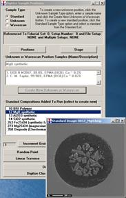
A new feature is that the program displays BMP electron image files of the standards in the standard blocks. The program looks for any BMP files in the StandardPOSFileDirectory as defined in the PROBEWIN.INI file [Standards] section, (defaults to UserDataDirectory if not defined) and if it finds a match to any file (first 4 characters) of the standard number it loads it. For example standard MgO entered as 12 in the STANDARD.MDB database could be a file called "0012_MgO_Block2.bmp" or "0012_Periclase_Block4.BMP". Both image files will be loaded during standard digitization (when the standard is clicked in the Digitize Sample Positions dialog ).
These BMP files should be placed in the Standard POS data folder as well, along with the *.POS files, so the Probe for EPMA programs can find them when digitizing coordinates on your standards
This can be used to check that you are on the correct standard or the image could be annotated to suggest places or grains to avoid during the standard digitization or acquisition process.
MatchStandardDatabase="DHZ.MDB"
The MatchStandardDatabase specifies the default standard database to be used for compositional matching in the Standard.exe application and the Probewin.exe application in the Analyze! window. The user may select other databases from three Match dialog.
The DHZ.MDB database is supplied as the default match database (Deere, Howie and Zussman Rock Forming Minerals, student edition), but the SRM.MDB (NIST Standard Reference Materials) and the DANA.MDB (non-silicate minerals from Dana’s Mineralogy) can also be specified. Note that the SRM.MDB and DANA.MDB standard databases must first be imported to a new database for use by the match feature.
The user may create additional standard databases as desired that are specific to their compositional matching requirements.
StandardCoatingFlag = 1 ; 0 = not coated, 1 = coated
StandardCoatingElement = 6 ; assume carbon
StandardCoatingDensity = 2.1
StandardCoatingThickness = 200 ; in angstroms
These parameters are the default parameters for the conductive coating on the standards. Values for all standards or individual standards can be edited in the program under the Standards menu. Note that these parameters are NOT used unless the user turns on this option for an unknown sample or group of unknown samples (see Calculation Options) from the Analytical | Analysis Options menu dialog.