Calibrate Peak Center
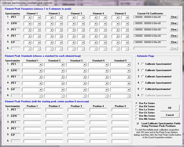
The Calibrate Peak Center option allows the user to specify a number of elements and corresponding standards for the program to perform multiple peak calibrations. After the peak centering has been performed the program will save the theoretical spectrometer positions along with the actual measured peak positions and a least squares fit to the data for the purpose of calculating a variable offset function which in turn is used to calculate the actual peak position of any element on that spectrometer/crystal combination.
The default constant "offset" from actual spectrometer position is calculated as follows:

where:  = the theoretical spectrometer peak
position
 = the actual or measured spectrometer
peak position
and is always applied unless the user performs the procedures described in this section. The default constant offset is usually sufficient if the miscalibration of the spectrometer mechanism is constant over the range of motion. However, if the offset varies as a function of spectrometer position, then the multiple peak calibration procedure will allow the use of variable offsets for each spectrometer-crystal combination for highest accuracy.
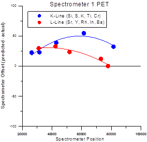
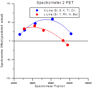
The multiple peak calibrations for each x-ray family (Ka, Kb, La, Lb, Ma and Mb) are stored in separate files which are named PROBEWIN-X.CAL where X is KA, KB, LA, LB, MA or MB depending on the line type. This due to the fact that slight differences in partially resolved alpha and beta-1,2 peaks behave differently for each line family. There the calibrations for each family are stored separately. This difference for K and L fits can be seen the figure at the end of this section.
Note that each spectrometer/crystal combination should be calibrated using multiple peaks. If less than three elements are specified the program will fit the data to a straight line. If less than two elements are specified the program will use a constant offset for the spectrometer correction which will have a similar accuracy to the default constant offset calculation.
Note also that a two crystal spectrometer will require two separate peak center procedures, one for each spectrometer/crystal combination although all tunable spectrometers can be calibrated automatically in a single run.
See the keyword "UseMultiplePeakCalibrationOffset" in the [software] section of the PROBEWIN.INI file for further instructions. This parameter must be set to a non-zero value to use this feature. Note that the calibration data is saved to an ASCII file called PROBEWIN-X.CAL and can be viewed using a text editor, but should not be edited by hand.

When performing multiple peak calibrations be sure to run graphical PHA distribution scans (from the PHA dialog which is accessed using the PHA button) using the lowest energy line specified for each spectrometer/crystal combination to make sure that the detector bias and gain are properly set. The baseline and window settings should be wide enough to allow for a range of energies since the entire spectrometer range will normally be utilized.
In addition, it is recommended that the count time in the Peak/Scan dialog be set to a sufficiently long time to provide proper statistics for the calibration, at least 20-40 seconds. Also each standard must be properly digitized and the position confirmed before the multiple peak calibration procedure is performed (it is important that the optical focus be precisely adjusted for each standard used in the procedure).
Use the Calibrate Parameters button to set the elements and standards for each spectrometer/crystal combination. To start a multiple peak center, check the Calibrate Peak Center checkbox, click OK and click the Start Peak Center button. To perform multiple peak centers on the other crystals, use the Move dialog to flip crystals and use the Calibrate Parameter dialog for each additional crystal.
When a spectrometer/crystal combination has been properly calibrated, the program will automatically load the "corrected" peak position for an element based on the fit to the measured spectrometer positions. This may be tested using the element/x-ray target positions in the Move dialog. The "corrected" spectrometer positions will also be utilized in the Elements/Cations dialog of Probe for EPMA for new elements not loaded from the element Setup database or another file or sample setup.


Spectrometer Calibration Offsets for Ka and La lines on PET Crystals
A modification allows the user to specify the starting peak position for the peak center procedure for each element on each spectrometer. This is especially useful in cases where the theoretical peak position is completely off the peak due to severe misalignment of the spectrometer. The starting peak center position loaded is by default based on the theoretical peak position or the previously stored actual peak position from the .CAL file (if available). Which default starting peak position is loaded depends on whether the Load Peak Center Start From Previous Peak Positions checkbox in the Calibrate Peak dialog box is checked (default is checked).
A new post-scan option allows the user to confirm that the peak position has been accurately determined by the software peak center method. Note that the post-scan range is 5% (+/- 2.5%) of the pre-scan range.
 Multiple Peak Calibration for Spectrometer to Angstroms
Calculations