Getting Started > Amplifiers > DCLAMP - Dynamic Clamp
WinWCP supports the Strathclyde Electrophysiology Software DCLAMP dynamic clamp based on the National Instruments cRIO-9076 Real Time Controller. The dynamic clamp permits the addition or subtraction of a simulated voltage- and time-dependent ionic conductance to/from a patch-clamped cell in current-clamp mode. A Hodgkin-Huxley voltage-dependent ionic current is simulated with bi-exponential decay kinetics is supported. Note. Contact [email protected] for details of the cRIO-9076 hardware and firmware required to implement DCLAMP.
Select Setup->DCLAMP Dynamic Clamp to open the dynamic clamp control panel.
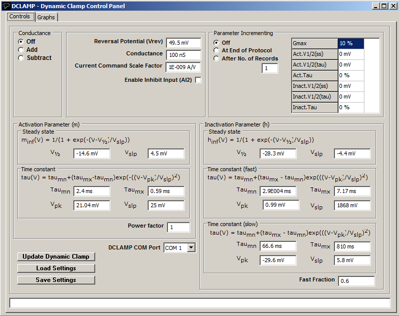
DCLAMP Com Port: Selects the serial port used to communicate with the cRIO-9076 controller.
Reversal Potential: The reversal potential of the simulated ionic current is defined in the Reversal Potential (Vrev) field.
Conductance (Gmax): The maximum conductance (nS) of the simulated conductance is defined in the Conductance field.
Current Command Scale Factor: The current command scaling factor (Amps/Volt) of the patch clamp is entered into Current Command Scale Factor field.
Enable Inhibit Input (AI2): Tick this option to enable inhibition of the simulated current in real time by a 5V signal applied to the AI2 input of the cRIO-9076 controller.
Conductance: Select the Add option to add the simulated current to the cell, Subtract to subtract it and Off to disable the conductance.
Activation Parameter (m): Defines the dependence of steady-state and time constant of the conductance activation parameter (m) on membrane potential.
Inactivation Parameter (h): Defines the dependence of steady-state and time constant of the conductance activation parameter (h) on membrane potential. Fast and slow kinetics are defined and the ration of fast to slow kinetics by the Fast Fraction field.
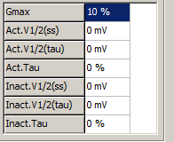
Parameter Incrementing: Conductance model parameters can be incremented at the end of a stimulus protocol by selecting the At End of Protocol option or after a number of records by selecting the After No. of Records option and entering the required number of records in the associated box.Increments (both positive and negative) can be applied to the maximum conductance (Gmax), half-maximal voltages of the activation (m) and inactivation (h) voltage-sensitivity curves and activation and inactivation time constants by entering non-zero step sizes into the increments table.
NOTE. It can take up to 45 seconds to completely update the voltage-sensitivity of the conductance model and during that period the conductance model will be in an intermediate state. Records acquired within the first 45 seconds after a model change should be discounted. Updates to Gmax are faster and are complete within 5 seconds.
Load/Save Settings: Click the Save Settings button to save the dynamic clamp conductance settings to a .DCS settings file. Click the Load Settings button to load settings from a .DCS file.
Update Dynamic Clamp: Updates dynamic clamp with current settings.
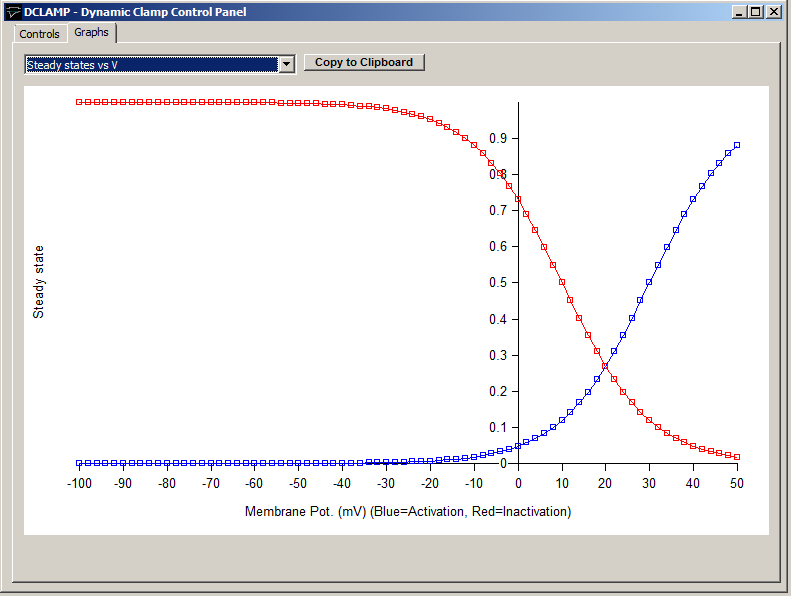
Graphs: The Graphs page shows the steady state activation- and inactivation-voltage and the activation and inactivation time constant-voltage curves for the current set of model parameters.The data points in these curves can be copied to the Windows clipboard by clicking Copy to Clipboard.