Getting Started > Amplifiers > Configuring Amplifier Support in WinWCP
To configure amplifier support select
Setup
Input Channels & Amplifiers
to open the Input Channels & Amplifiers Setup dialog box.
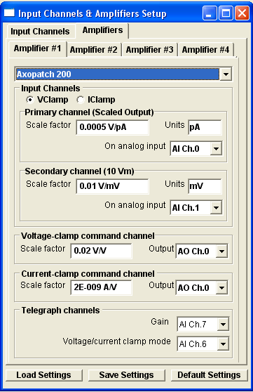
Select the Amplifiers tab and choose the amplifier to be configured (Amplifier #1 if only one amplifier is in use), then select your type of amplifier in the amplifier list.
The amplifier configuration table shows the default primary and secondary input channels, voltage and current command output channels and gain and mode telegraph input channels (if these are required by the amplifier).
The basic (at minimum gain) scaling factors and units for the current and voltage outputs and the current and voltage command inputs are also displayed.
If required, the Gain and Voltage/current clamp mode telegraph inputs can be changed to another analog input channel. However, if this is done, the physical connections between the amplifier and the laboratory interface must be adjusted to match. Telegraphs can also be disabled by selecting Off as the input channel. When telegraphs are disabled, gain and/or voltage/current clamp mode can be entered manually by the user.
If necessary, primary and secondary channel scaling factors, units, voltage- and current-clamp command scaling factors can be altered by the user. This is most likely to be case for the command scaling factors where where a range of division factors are available on most common patch clamp amplifiers. The default settings are set to the most commonly used stimulus scalings (0.02 or 0.1) for the amplifier. In the case of amplifiers where the primary/secondary channels switch output signals in current- or voltage-clamp mode, two different primary and secondary channel scaling factors can be entered, by selecting the ICLAMP orVCLAMP options.
Note that, in the case of amplifiers
Manual amplifier configuration
If the amplifier in use is not specifically supported by WinWCP, current and voltage scaling information can still be entered manually by the user. To enter up a manual amplifier configuration, select
Manual Gain Entry
as the amplifier type and enter the following information.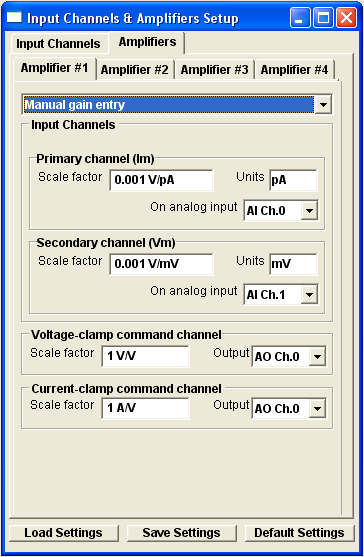
Primary Channel (Im)
The amplifier membrane current output should be connected to this input channel (AI Ch.0 for Amplifier#1). Enter the measurement units of the current (pA, nA, uA, mA, A) into the Units box and the amplifier current scaling factor of the amplifier at minimum gain in V/units into the Scale factor box. The scaling factor can typically be obtained by reading the minimum gain setting of the rotatable current gain switch, found on most patch-clamp amplifiers (e.g. a minimum gain settings of 1mV/pA is equivalent to a scaling factor of 0.001V/pA.)
Secondary Channel (Vm)
The amplifier membrane potential output should be connected to this input channel (AI Ch.1 for Amplifier#1). Enter the measurement units of the current (mV) in the Units box and the amplifier voltage scaling factor, in V/Units, into the Scale factor box. Most amplifiers have a fixed scaling factor of 0.01 V/mV.
Voltage-clamp command channel
Analog output (AO Ch.0 for Amplifier#1) should be connected to the amplifier command voltage input. Enter the voltage-clamp command potential scaling factor (membrane potential/command voltage) into the Scale factor box. (A label specifying the command voltage scaling factor can usually be found beside the command voltage input socket on the amplifier. Typical values are 0.1 V/V or 0.02 V/V)
Current-clamp command channel
Enter the current-clamp command potential scaling factor (membrane current/command voltage) into the Scale factor box. The current clamp command scaling factor can usually be found in the amplifier user manual. Typical values are between 10-9 A/V and 10-10 A/V. (Usually the current command signal is applied to the same input on the amplifier as the voltage command (AO Ch.0 for Amplifier#1), however on some there may be a separate current command input.)
Saving/Loading Settings
Amplifier and input channel settings can be saved to a settings file by clicking the Save Settings button and saving the settings to an XML settings file. Settings can be reloaded from a settings file by clicking Load Settings and selecting the file.The default scaling and channel settings for an amplifier can be reset by clicking the Restore Default Settings button. Default settings are also loaded whenever the amplifier type is changed.