Recording Experimental Signals > Creating Stimulus Protocols > Recording Settings
Select the Recording tab page to set the number of recording sweeps to be acquired during the protocol and the number of analog channels, samples/channel, duration, and sweep repetition interval.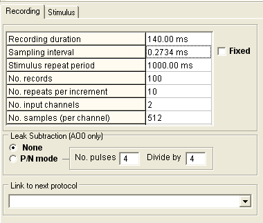
Recording duration: the duration of the recording sweep. (Note. When the Fixed sampling interval option is selected, this entry is defined by the Sampling interval setting.)
Sampling interval: Time interval between samples on each channel. When the Fixed option is selected, the sampling interval entered here defines the duration of the Recording duration ( Sampling interval x No. samples per channel). When the Fixed option is not selected, sampling interval is set by the Recording duration ( Recording duration / No. samples per channel).
Stimulus repeat period: the time interval between successive recording sweeps in the protocol.
No. records: The number of records to be acquired during the protocol.
No. repeats per increment: For incremented step waveforms, the number of times a stimulus is to be repeated without incrementing the step size.
No. input channels: The number of analog input channels to be acquired. Channels are always acquired in sequence from Ch.0 upwards, i.e. No. input channels=1, selects Ch.0; No. input channels=2 selects Ch.0 & Ch.1 etc.
No. samples: The number of samples to be acquired per input channel. The minimum is 256 samples per channel increasing in steps of 256. The maximum ranges from 16184/No. Channels - 1048576/No. Channels, depending on the laboratory interface in use.
External Stimulus trigger (Y/N): Enables the stimulus protocol to be triggered by an external TTL pulse instead of the internal timer. When set to Y, the stimulus repeat period is ignored and the stimulus protocol begins when a TTL pulse is received on the External Stimulus Trigger Input (See laboratory interface card connections tables in section 1.)
Leak subtraction settings
A protocol can be programmed to add digital leak subtraction records using the P/N mode option. When this option is selected, a series of additional recording sweeps are generated for each record defined in the protocol, using an inverted and scaled down version of the command voltage waveform. A digital average is obtained from these records and stored in the data file as a “LEAK” record, along with the basic “TEST” record.
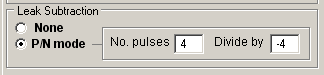
You can change the number of pulses used to compute the “LEAK” record and division factor by altering the values in the boxes shown. The default values are 4 leak records with voltage waveform divided by –4.
Note that subtraction of the “LEAK” from “TEST” records is done using the leak subtraction module. (See section 13 for details.)
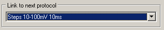
Protocol linking
Recording normally stops when the requested sequence of records within a protocol is completed. Protocols can, however, be linked together by selecting a protocol from the Link to next protocol list, so that on completion of the first protocol, control is transferred to the linked protocol.