Non-stationary Noise Analysis > Analysing Synaptic Current Fluctuations
The WinWCP non-stationary noise analysis module can be used to compute the time course of residual current fluctuations between individual current records and the average current time course, and plot the variance of these fluctuations vs mean current at each sample time point during the decay of the current. The average number of ion channels contributing to the ionic current and the single-channel current can then be estimated by fitting a parabolic function to the variance vs. mean plot.
Select
Analysis
Non-stationary noise analysis
to open the non-stationary variance analysis window.
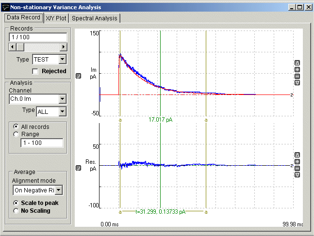
The upper trace in the signal display panel shows a selected individual signal record (blue) with the average of all the records in the file superimposed in red. The lower trace shows the residual difference (Res) between the signal record and the average.
To generate a variance vs mean plot and estimate single-channel current and channel number from a series of synaptic current records:
1) If there is more than one signal channel, select the channel containing the current signal to be analysed from the Channel list.
2) Optional. To use a specific record type only, change the Type list from ALL to the selected type (TEST, LEAK, EVOK, MINI, FAIL, TYP1, TYP2, TYP3).
3) Select the All Records option to use all records of the selected type. To use a sub-range of the records within the file, Select Range and enter the range of records in the box.
4) If synaptic currents are being analysed, select the Scale to Peak option to scale the average current to the peak amplitude of each current record before the subtraction to produce the residual variance. Select No Scaling if the unscaled average is to be subtracted..
5) Optional. If the starting time of each signal varies significantly from record to record, it can be re-aligned with the average current before subtraction to produce the residual. Set the Alignment mode to On Positive Rise for positive-going signal and On Negative Rise for negative signals.
6) Select the region of the signal waveform (the decay phase in the case of synaptic currents) to be included in the variance vs. mean plot using the pair of (a-a) analysis region cursors.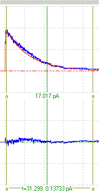
7) Click the X/Y Plot tab to switch to the X/Y Plot page.
Select Mean from the X Axis variable list and Variance from the Y Axis list, then click the New Plot buttonto generate the variance vs mean plot, s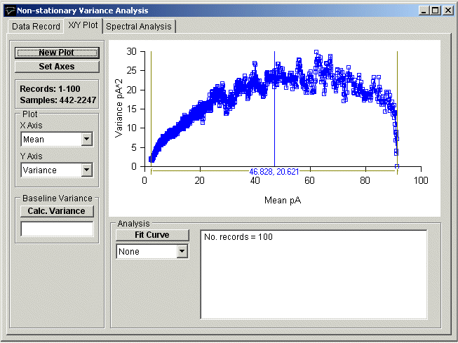
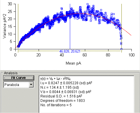
8) To fit a parabola to the curve:
a) Select Parabola from the curve fitting list to fit the equation y(x) = Vb + Iu*x + x2/Nc
(where Iu is the single-channel current, Nc is the number of ion channels and Vb is the background variance).
b) Define the region of the variance vs mean plot to be fitted to, using the analysis region cursors (f-f).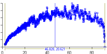
c) Click the Fit Curve button, set (optional) the initial parameter guesses and click the OK button to fit the curve.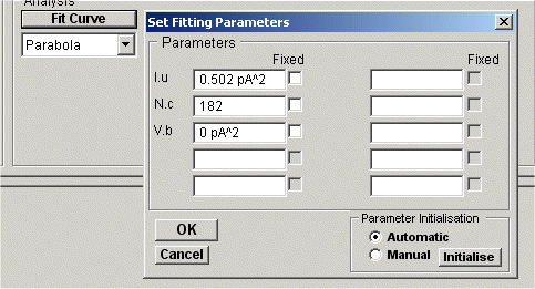
The best fitting parabola is superimposed (in red) on the variance vs. mean plot. The estimated single-channel current (Iu) and number of channels (Nc) are displayed in the curve fitting results box, along with an estimate of the background variance (Vb).