Getting Started > Laboratory Interfaces > Instrutech ITC-16/18
Instrutech Corp www.instrutech.com (now handled by Heka Electronik GmbH)
The Instrutech ITC-16 and ITC-18 interfaces are self-contained, 19” rack-mountable, mains-powered digitiser units with BNC I/O sockets attached to the host computer via a digital interface card and cable. Both the ITC-16 and ITC-18 support 8 analog input channels, 4 analog outputs and 8 digital outputs.
Note. The Instrutech ITC-1600, LIH8+8 and USB-18 are not currently supported by WinWCP.
Software installation
WinWCP uses the Instrutech device interface libraries for the ITC-16/18 family. Details for steps (1)-(3) can be found in the Instrutech Data Acquisition Interface user manual.
1) Install the Instrutech interface card in an expansion slot.
2) Attach the ITC-16 or ITC18 unit to the card.
3) Install the Instrutech Device Driver software supplied with the card (or downloaded from www.instrutech.com)
4) Reboot the computer.
5) Run the Instrutech test program installed with the device driver to test whether the software installed OK.
6) Run WinWCP and select from the main menu
Setup
Laboratory Interface
to open the Laboratory Interface Setup dialog box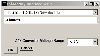
then select Instrutech ITC-16/18 (New driver) from the laboratory interface options list. Note, on systems with Instrutech’s older device driver software installed, it may be necessary to select either Instrutech ITC-16 (Old Driver) or Instrutech ITC-18 (Old Driver) depending upon which interface unit is installed.
Instrutech ITC-16/18: I/O Panel Connections
Signal input and output connections are made via the BNC sockets on the front of the ITC-16/18 unit.
|
Instrutech ITC-18 |
||
|
Analog Input |
I/O Panel |
Notes |
|
Ch. 0 |
ADC Input 0 |
|
|
Ch. 1 |
ADC Input 1 |
|
|
Ch. 2 |
ADC Input 2 |
|
|
Ch. 3 |
ADC Input 3 |
|
|
Ch. 4 |
ADC Input 4 |
|
|
Ch. 5 |
ADC Input 5 |
|
|
Ch. 6 |
ADC Input 6 |
|
|
Ch. 7 |
ADC Input 7 |
|
|
Analog Output |
|
|
|
Ch. 0 |
DAC Output 0 |
|
|
Ch. 1 |
DAC Output 1 |
|
|
Ch. 2 |
DAC Output 2 |
|
|
Ch. 3 |
DAC Output 3 |
|
|
Trigger Inputs |
|
|
|
Ext. Sweep Trigger |
Trig In |
|
|
Ext. Stimulus Trigger |
Trig In |
See Note 1 |
|
Digital Output |
|
|
|
Ch. 0 |
TTL Output 0 |
|
|
Ch. 1 |
TTL Output 1 |
|
|
Ch. 2 |
TTL Output 2 |
|
|
Ch. 3 |
TTL Output 3 |
|
Note 1. An active-high TTL pulse on this input triggers the start of a stimulus program which has been set up with the External Stimulus Trigger = Y option.
Instrutech ITC-16/18: Troubleshooting
WinWCP requires Instrutech's combined device driver library ITCMM.DLL (released late 2001). It may not work with earlier libraries.