Getting Started > Laboratory Interfaces > Axon Instruments Digidata 1320
Axon Instruments Inc. (now owned by Molecular Devices, www.moleculardevices.com)
The Digidata 1320 Series (1320A, 1322) interfaces consist of self-contained, mains-powered digitiser units with BNC I/O sockets attached to the host computer via a SCSI (Small Computer Systems Interface) interface card and cable. A number of versions are available including the 1320A and 1322A. The 1322A supports sampling rates up to 500 kHz (16 bit resolution) on up to 16 channels. It has a fixed input and output voltage range of 10V and supports 4 digital output channels..
Software Installation
WinWCP uses Axon’s standard software library (AxDD132x.DLL) for the Digidata 1320 Series. Details for steps (1)-(5) can be found in Axon’s Digidata 1320 Series Operator’s Manual.
1) Install the Axon SCSI card in a PCI expansion slot.
2) Attach the Digidata 1320 to the SCSI card and switch on the computer and 1320.
3) Install the AxoScope software supplied with the Digidata 1320.
4) Reboot the computer.
5) Run AxoScope to ensure that the software installed OK.
6) Run WinWCP and select from the main menu:
Setup > Laboratory Interface
to open the Laboratory Interface Setup dialog box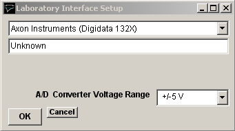
then select Axon Instruments (Digidata 132X) from the laboratory interface list.
Signal input / output connections
Signal input and output connections are made via the BNC sockets on the front of the Digidata 1320 Series digitiser unit.
|
Digidata 132X Series |
||
|
Analog Input |
I/O Panel |
Notes |
|
Ch. 0 |
Analog In 0 |
|
|
Ch. 1 |
Analog In 1 |
|
|
Ch. 2 |
Analog In 2 |
|
|
Ch. 3 |
Analog In 3 |
|
|
Ch. 4 |
Analog In 4 |
|
|
Ch. 5 |
Analog In 5 |
|
|
Ch. 6 |
Analog In 6 |
|
|
Ch. 7 |
Analog In 7 |
|
|
Analog Output |
|
|
|
Ch. 0 |
Analog Out 0 |
|
|
Ch. 1 |
Analog Out 1 |
|
|
Trigger Inputs |
|
|
|
Ext. Sweep Trigger |
Trigger In Start |
|
|
Ext. Stimulus Trigger |
Trigger In Start |
See Note 1 |
|
Digital Output |
|
|
|
Ch. 0 |
Digital Out 0 |
See Note 2 |
|
Ch. 1 |
Digital Out 1 |
|
|
Ch. 2 |
Digital Out 2 |
|
|
Ch. 3 |
Digital Out 3 |
|
Note 1. An active-high TTL pulse on this input triggers the start a stimulus program which has been set up with the External Stimulus Trigger = Y option.
Note 2. The Digidata 1320 Series only supports 4 digital output lines.
Troubleshooting
When multiple analog input channels are being sampled and the sampling interval is greater than 10 ms, samples get mixed up between channels. This problem can be seen to occur also with AxoScope, suggesting a bug in the Digidata 1320 firmware or AXDD132X.DDL library. The only limited solution at present is to increase the number of samples per record to ensure that the sampling interval is less than 10 ms.