CED 1902 Amplifier
From WinWCP V5.3.8
Getting Started > Amplifiers > CED 1902 Amplifier
Cambridge Electronic Design Ltd (www.ced.co.uk)
The Cambridge Electronic Design 1902 is a computer-controlled amplifier with built-in isolation circuits for recording ECG and EMG signals from humans, and a bridge circuit for recording from tension or pressure transducers. It can also be used to record extracellular electrical activity from nerve and muscle. It has two inputs.
· The Electrodes input is an electrically isolated differential amplifier input used to record ECG, EMG and similar signals. Isolation makes it safe to attach recording leads to human subjects.
· The Transducer input is a differential amplifier input used to record from transducers such as force and pressure transducers. It is not isolated.
Connections
In order to control the amplifier, the CED 1902 serial communications cable must be connect to a serial port (COM1 or COM2). The analog output of the CED 1902 should also be connected to analog input Ch.0 of the laboratory interface. The amplifier gain setting is taken into account by WinWCP in scaling the signal level on this channel.
Control Panel
Select
Setup
CED 1902 Amplifier
to open CED 1902 control panel
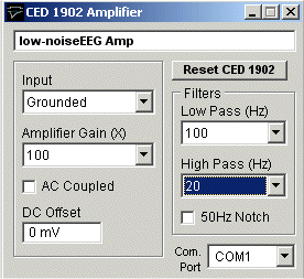
The following amplifier settings can be configured using the panel:
COM Port: Selects the serial port used to communicate with the 1902.
Input: Selects the amplifier input; Grounded to connect the input to ground (i.e. there is no signal.), Single Ended for the transducer input in singled ended (i.e. non-differential mode), Normal Diff+ for the Transducer input in differential amplifier mode, Inverted Diff- for the transducer input in differential mode with the signal inverted, or Isolated EEG for the electrically isolated differential input.
Note. Normal Diff+ mode is used when recording from a force or pressure transducer and Isolated EEG used when making EMG, ECG recordings.
Amplifier Gain: Sets the gain of the CED 1902 amplifier. The range of gain settings depends on which input is in use. When using the Transducer input there are 11 gain settings (X1, X3, X10, X30, X100, X300, X1000, X3000, X10000, X30000, X10000). When using the Electrodes input (X100, X300, X1000, X3000, X10000, X30000, X100000, X300000, X1000000, X3000000, X1000000). Note. When CED 1902 is selected as the Amplifier in the Recording setup dialog box, the gain setting is automatically included in the scaling of input channel 0
Low Pass Filter: Sets the cut-off frequency of the CED 1902’s built-in low pass filter. The filter can be set to None (out of use), 1000Hz, 500Hz, 100Hz. The low pass filter removes signal frequencies signal higher than the cut-off, smoothing the signal.
High Pass Filter: Sets the cut-off frequency of the CED 1902’s built-in high pass filter. The filter can be set to None (out of use), 50Hz, 100Hz, 200Hz. The high pass filter removes signal frequencies signal lower than the cut-off, removing steady and slowly changed components of the signal.
AC Coupled: Check this box to make the CED 1902 input AC (alternating current) coupled. In this mode only variations in the signal are allowed through to the amplifier, constant (DC) levels are blocked. (AC coupling should beused with EMG and ECG recordings but not with force or pressure transducer recordings.)
50 Hz Filter: Enable/disables a notch filter which selectively removes frequencies around 50Hz. (Used to remove 50Hz interference from mains power lines).
DC Offset: The DC Offset facility adds or subtracts a DC voltage level from the input. The offset range depends upon the input mode (Normal Diff+ and Inverted Diff- = +/-0.5mV, Single Ended =+/-500mV, Electrodes = +/-0.1mV). The offset facility is often used to cancel out the standing DC voltage signal from tension transducers.