Displaying Records Stored on File > Measuring Signal Levels
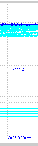 To measure the signal at any point on the displayed record, use the mouse to drag the vertical readout cursor to the desired part of the trace. Fine positioning of the cursor can be achieved by pressing the left or right arrow keys with the mouse pointer over the selected cursor.
The signal level of the trace(s) at the cursor position is displayed at the bottom of each channel. Time measurements are made relative to the start of each record and (in brackets) relative to the location of the t=0 cursor. Signal levels are measured relative to each channel’s horizontal zero level cursor.
Cursor measurements can be written to the WinWCP log file by clicking the Save (F1) button. The Centre Cursor button places the readout cursor to the centre of the displayed region.
Zero levels
The signal zero level for a channel can be defined in either of two ways. In From record mode, it is computed as the average level from a defined portion of each record. In Fixed mode, it is fixed at a level defined by the user and does not vary from record to record.
From record mode
 Use the from record zero mode when you want to measure transient signals, which are superimposed upon a baseline level which may be varying from record to record. To set the zero level from a portion of the signal record itself in from record mode:
1) Move the mouse pointer over the horizontal zero level cursor of the channel you want to change. (The mouse pointer turns into an up/down arrow.)
2) Slide the mouse pointer horizontally until it overlies the region of the record which is to be defined as the zero level.
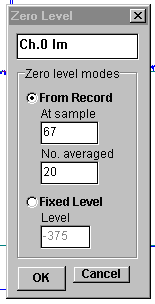
3) Click the right-hand mouse button to open the zero level dialog box.
4) Select the From Record option.
5) The zero level is computed, for each record, from the average of a series of (default=20) samples starting at the sample indicated in the At sample box. If you want to change the number of samples averaged to compute the zero level, change the value in the No. averaged box.
6) Click the OK button to use the new zero level.
Fixed Level mode
 Use the fixed level zero mode when you want to make measurements relative to a fixed absolute level. To fix the zero level at a constant value to be used for all records in the file:
1) Move the mouse pointer over the horizontal zero level cursor of the channel you want to change. (The mouse pointer turns into an up/down arrow.)
2) Hold down the left mouse button and drag the zero level cursor vertically until it is at the desired level.
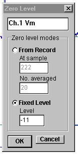
3) Click the right- mouse button to open the zero level dialog box.
4) Select the Fixed option. The vertical position of the fixed baseline is indicated (in A/D converter units) in the Level box. You can set the zero level by entering a value.
5) Click the OK button to use the new zero level.
Fixed mode is typically used for the membrane potential measurements in voltage/patch clamp studies of voltage-activated current.(Note. Entering a value of zero into the Level box sets the zero level to the true zero voltage level for the channel)