Getting Started > Amplifiers > Channel Calibration Table
 WinWCP displays the signals stored in each signal channel in the units appropriate to each channel. The names, units and scaling information for each channel are entered into the channel calibration table which can be displayed by selecting the Input Channels tab in the Input Channels & Amplifiers dialog box.
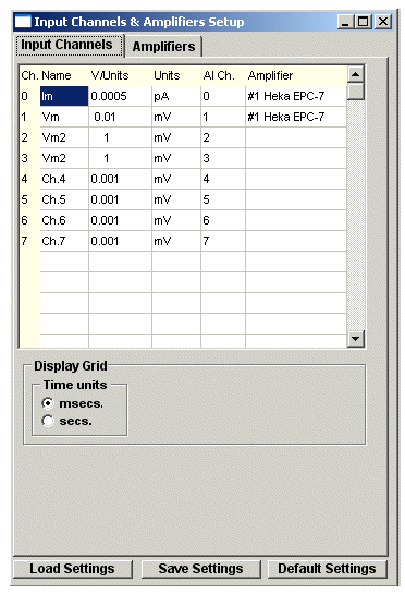
The channel calibration table settings for the patch clamp current and voltage channels are automatically configured with appropriate names, units and V/Units scaling when an amplifier is selected from the Amplifiers list. However, when no amplifier is selected for use (i.e. Amplifier=None) the calibration information for a channel must be entered directly into the table.
There are 5 entries in the table for each channel.
Name: A 1-4 letter name used to identify the source of the channel (e.g. Vm, Im).
V/Units: The scaling factor relating the voltage level at the inputs of the A/D converter (in V) to the actual signal levels in each channel (in the units defined in the Units column).
Units: The measurement units of the signal (e.g. mV, pA etc.).
ADC Ch.: The analog/digital converter input channel from which the signal for this channel is being acquired. (Note. Signal channel to analog input mapping is currently only available with National Instruments interface cards.)
Amplifier: Indicates whether an amplifier has been defined for this channel.
For example, if the membrane voltage output of your amplifier supplies a signal which is 10X the measured membrane potential of the cell, and the units have been defined as mV, then the appropriate V/Units setting is 0.01 (since the amplifier voltage output is 0.01 Volts per mV).
Amplifier
Display Grids and Time Units
The Time Units options determine the units (secs or msecs) used to display time intervals in signal display windows.