Getting Started > Laboratory Interfaces > Molecular Devices Digidata 1440A
Molecular Devices Corporation (www.moleculardevices.com)
The Digidata 1440A interface consists of self-contained, mains-powered digitiser unit with BNC I/O sockets attached to the host computer via a USB 2.0 port. The 1440A supports sampling rates up to 250 kHz (16 bit resolution) on up to 16 channels. It has a fixed input and output voltage range of 10V and supports 4 analog output channels and 8 digital output channels.
Software Installation
WinWCP uses Axon’s standard software library (AxDD1400.DLL) for the Digidata 1400 Series. Details for steps (1)-(5) can be found in Axon’s Digidata 1440A Manual.
1) Install the AxoScope (or PCLAMP ) software supplied with the Digidata 1440.
2) Reboot the computer.
3) Attach the Digidata 1440A to a USB port and turn it on.
4) Run WinWCP and select from the main menu
Setup > Laboratory Interface
to open the Laboratory Interface Setup dialog box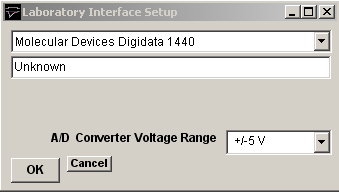
then select Molecular Devices (Digidata 1440) from the laboratory interface list.
Analog Input Offset Calibrations
The offset calibration values for the Digidata 1440 analogue input channels can be modified by creating a file called "Digidata 1440 adc offsets.txt" in the settings folder U:\users\Public\Public Documents\SESLabIO containing a list of offsets for each channel. The file should contain a list of 16 offset values (in mV) to be subtracted from each channel signal, e.g.
3.5
4.0
1.0
-1.0
...
A file Digidata 1440 calibration factors.txt containing the analogue input and output offset and gain correction factors in current use in the Digidata 1440 is also created in the settings folder when WinWCP is started.
Signal input / output connections
Signal input and output connections are made via the BNC sockets on the front of the Digidata 1440A digitiser unit.
|
Digidata 1440A |
||
|
Analog Input |
I/O Panel |
Notes |
|
Ch. 0 |
Analog Input 0 |
|
|
Ch. 1 |
Analog Input 1 |
|
|
Ch. 2 |
Analog Input 2 |
|
|
Ch. 3 |
Analog Input 3 |
|
|
Ch. 4 |
Analog Input 4 |
|
|
Ch. 5 |
Analog Input 5 |
|
|
Ch. 6 |
Analog Input 6 |
|
|
Ch. 7 |
Analog Input 7 |
|
|
Analog Output |
|
|
|
Ch. 0 |
Analog Out 0 |
|
|
Ch. 1 |
Analog Out 1 |
|
|
Ch. 2 |
Analog Out 2 |
|
|
Ch. 3 |
Analog Out 3 |
|
|
Trigger Inputs |
|
|
|
Ext. Sweep Trigger |
Start |
|
|
Ext. Stimulus Trigger |
Start |
See Note 1 |
|
Digital Output |
|
|
|
Ch. 0 |
Digital Output 0 |
|
|
Ch. 1 |
Digital Output 1 |
|
|
Ch. 2 |
Digital Output 2 |
|
|
Ch. 3 |
Digital Output 3 |
|
|
Ch. 4 |
Digital Output 4 |
|
|
Ch. 5 |
Digital Output 5 |
|
|
Ch. 6 |
Digital Output 6 |
|
|
Ch. 7 |
Digital Output 7 |
|
Note 1. An active-high TTL pulse on this input triggers the start of a stimulus program which has been set up with the External Stimulus Trigger = Y option.