Axon Instruments Digidata 1200
From WinWCP V5.3.8
Getting Started > Laboratory Interfaces > Axon Instruments Digidata 1200
Axon Instruments Inc.
(now owned by Molecular Devices, www.moleculardevices.com)
The Digidata 1200, 1200A and 1200B interface boards fully supports all WinWCP features. They have a 330 kHz maximum sampling rates and 4 programmable input voltage ranges (10V, 5V, 2.5V, 1.25V). Inputs to and outputs from the board are via BNC connectors on an I/O box, connected to the board via a shielded ribbon cable. In order to use WinWCP with a Digidata 1200, the following computer system resources must be available for use by the Digidata 1200.
· I/O port address 320-33F (Hex)
· DMA channels 5 and 7
Software Installation
1) Install the Digidata 1200 card into an ISA computer expansion slot, and attach it to its BNC I/O panel using the shielded ribbon cable supplied with the card.
2) Install the WinWCP Digidata 1200 driver software for your Windows operating system, by running the appropriate installation batch file.
If you are running Windows 95, 98 or Me, select WinWCP\Digidata 1200 Drivers\Install Digidata 1200 driver (Win95/98/Me) from the Programs menu.
If you are running the Windows NT, 2000 or XP, select WinWCP\Digidata 1200 Drivers\Install Digidata 1200 driver (Win NT/2000/XP). (Note. WinWCP does not use the standard Axon Instruments Digidata 1200 device driver).
3) Reboot the computer.
4) Run WinWCP and select from the main menu
Setup > Laboratory Interface
to open the Laboratory Interface Setup dialog box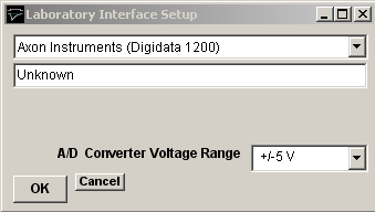
then select Axon Instruments (Digidata 1200) from the list of laboratory interface options.
Signal input / output connections
Signal input and output connections are made via the BNC sockets on the front and rear of the Digidata 1200 I/O box.
|
Digidata 1200 |
||
|
Analog Input |
I/O Panel |
Notes |
|
Ch. 0 |
Analog In 0 |
|
|
Ch. 1 |
Analog In 1 |
|
|
Ch. 2 |
Analog In 2 |
|
|
Ch. 3 |
Analog In 3 |
|
|
Ch. 4 |
Analog In 4 |
|
|
Ch. 5 |
Analog In 5 |
|
|
Ch. 6 |
Analog In 6 |
|
|
Ch. 7 |
Analog In 7 |
|
|
Analog Output |
|
|
|
Ch. 0 |
Analog Out 0 |
|
|
Ch. 1 |
Analog Out 1 |
|
|
Trigger Inputs |
|
|
|
Ext. Sweep Trigger |
Gate 3 |
|
|
Ext. Stimulus Trigger |
Gate 3 |
See Note 1 |
|
Digital Output |
|
|
|
Ch. 0 |
Digital Out 0 |
See Note 2 |
|
Ch. 1 |
Digital Out 1 |
|
|
Ch. 2 |
Digital Out 2 |
|
|
Ch. 3 |
Digital Out 3 |
|
Note 1. An active-high TTL pulse on this input triggers the start a stimulus program which has been set up with the External Stimulus Trigger = Y option.
Note 2. WinWCP only supports digital output lines 0-3 of the Digidata 1200.
Troubleshooting
There are two known problems which will prevent WinWCP from recording from a Digidata 1200’s analog input channels.
I/O port conflict. The Digidata 1200 default I/O port addresses span the range 320H-33AH. These settings conflict with the default MIDI port setting (330H) of Creative Labs. Sound-Blaster 16 and similar sound cards. There are a number of solutions to this problem.
1) Change the Sound-Blaster MIDI port setting to a value higher than 33AH.
2) Remove the Sound-Blaster card (or disable it using the BIOS setup if it is built in to the computer motherboard).
DMA channel conflicts. WinWCP requires DMA channels 5 and 7 to support the transfer of data to/from PC memory and the Digidata 1200. Many sound cards also make use of DMA 5 and can interfere with the operation of the Digidata 1200.