Getting Started > Amplifiers > Configuring the NPI ELC_03XS Amplifier
The NPI ELC-03XS Amplifier provides current and voltage and gain telegraph outputs on the front panel of the amplifier. Up to 4 NPI ELC-03XS amplifiers can be supported.
For each ELC-03XS in use, connections must be made between the Current Output, Potential Output and Command Input signal channels, Current and Potential Gain telegraph channels, and the analogue inputs of the laboratory interface. Connections must also be established between two analogue outputs and the Command Input and Stimulus Inputs
The Current Output channel, attached to the WinWCP primary input monitors the current signal in both voltage- and current-clamp operating modes. In voltage clamp mode, the cell potential, attached to the WinWCP secondary input, is obtained from Command Input and, in current-clamp mode from the Potential Output. The current- voltage-clamp mode switching between the Potential Output and Command Input can be accomplished either by physically changing the signal cable attachments or by reassigning analogue inputs using software.
Physically switched Secondary Input Switching
To configure WinWCP to use an NPI ELC-03XS as Amplifier #1, select NPI ELC-03XS as the amplifier type on the Amplifier #1 page of the Input Channels & Amplifiers Setup dialog box, as shown below.
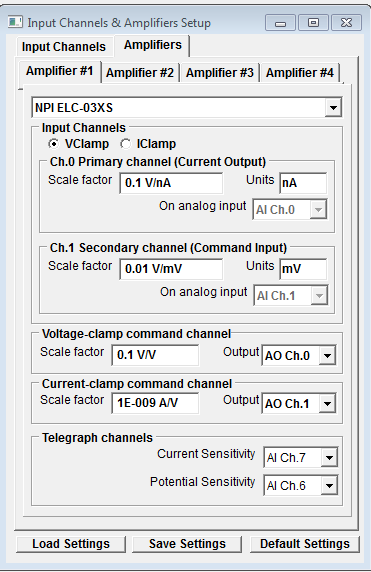
The default connections are:
|
|
Primary Ch. |
Secondary Ch. |
|
|
|
|
|
|
ELC-03XS |
Current Output |
VC mode |
CC Mode |
Potential Telegraph |
Gain Telegraph |
Command Input |
Stimulus |
|
Laboratory |
AI 0 |
AI 1 |
AI 1 |
AI 6 |
AI 7 |
AO 0 |
AO 1 |
The secondary input channel (AI1) must be physically switched between Command Input and Potential Output when the patch clamp is switched from voltage- to current-clamp mode. This can be accomplished by physically swapping the coaxial signal cables or using a BNC switch box. Note that, in voltage-clamp mode, Command Input has two connections to it (AO 0 and AI 1).
Software switched Secondary Channel Switching
Voltage/current-clamp mode switching of the Command Input and Potential Output channels can be accomplished automatically by attaching the Command Input and Potential Output outputs to different analogue input channels and remapping the analogue input to the secondary channel (Ch.1) using software.
Software channel switching can be configured by selecting the IClamp option on the Amplifier #1 page and selecting a free analogue input (e.g. AI 4) for the Ch.1 Secondary Channel, as shown below.
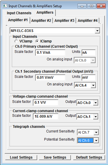
The connections for a software switched secondary channel are shown below.
The default connections are:
|
|
Primary Ch. |
Secondary Ch. |
|
|
|
|
|
|
ELC-03XS |
Current Output |
VC mode |
CC Mode |
Potential Telegraph |
Gain Telegraph |
Command Input |
Stimulus |
|
Laboratory |
AI 0 |
AI 1 |
AI 4 |
AI 6 |
AI 7 |
AO 0 |
AO 1 |
Note that Command Input has two connections to it (AO 0 and AI 1).