Simulations > Voltage-activated Current Simulation
The voltage-activated currents module simulates the currents evoked in response to a series of rectangular voltage steps, using the Hodgkin-Huxley equations. Both activation and inactivation kinetics are modelled. Two channels are generated, membrane potential and membrane current. The model also simulates the effects of patch clamp pipette access conductance on measured currents. The Hodgkin-Huxley simulation can be used to test the leak subtraction module and the Hodgkin-Huxley functions in the curve fitting module.
The currents, are modelled by the equation

where V is the voltage level to which the cell potential is stepped, Vh is the initial holding voltage, Vrev is the reversal potential for the conductance, Gmax is the maximal conductance, Taum the activation (m) time constant, Tauh the inactivation (h) time constant, and p the power to which the activation parameter is raised, m,(V) and h (V) are the steady-state values of the activation and inactivation parameters, respectively, defined by Boltzmann functions, m(V) and h(V) are bell-shaped functions.
To create a data file containing simulated voltage-activated currents:
Create a new data file to hold the records, by selecting
File
New
and entering the name of a new data file.
Select
Simulations
Voltage-activated currents
to open the simulation window.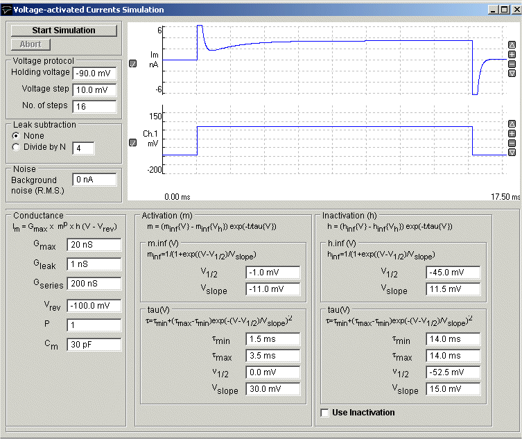
Set the simulated EPSC properties:
Voltage Protocol: Enter the voltage-clamp holding voltage into the Holding voltage box, the number of simulated voltage steps to be created in the No. of steps box, and the increment in voltage between steps in the Voltage step box.
Leak Subtraction: If leak subtraction records are to be created, select Divide by N and enter the P/N divide factor.
Noise: Enter the standard deviation of the gaussian background noise to be added to the signals in the Background noise box.
Conductance: Enter the maximum conductance for the voltage-activated current being modelled in the Max. conductance box. Enter the reversal potential for the voltage activated conductance in the Reversal potential box. Enter the cell’s non-voltage dependent leak conductance in the Leak conductance box. Enter the access conductance of the patch pipette used to patch clamp the cell in the Pipette conductance box. (Note that if the pipette access conductance is less than 5X the cell membrane conductance, then pipette series resistance artefacts will occur.). Enter the cell capacity in the Cell capacity box. This determines the size of the capacity current artifact at the beginning and end of the voltage step.
Activation (m): The Activation (m) settings group determines the voltage and time dependence of the Hodgkin-Huxley activation parameter, m.Enter the power to which the activation parameter, m, is to be raised to in the Activation power factor box. (Default =3, typical of sodium currents). The voltage dependence of steady-state activation is set by the Boltzmann function, minf(V), defined by its voltage of half maximal activation V1/2 and slope Vslope. The voltage dependence of the activation time constant, tau(V) is set by a bell shaped function, which varies the time constant between the minimum, tmin and maximum tmax, with tmax occurring at V1/2 and the steepness of the cursor defined by Vslope.
Inactivation (h): The Inactivation (h) settings group determines the voltage and time dependence of the activation parameter, h. To enable the inactivation parameter, check the Inactivation in use box. The voltage dependence of steady-state activation is set by the Boltzmann function, minf(V), defined by its voltage of half maximal activation V1/2 and slope Vslope. The voltage dependence of the activation time constant, tau(V) is set by a bell shaped function, which varies the time constant between the minimum, tmin and maximum tmax, with tmax occurring at V1/2 and the steepness of the cursor defined by Vslope. Enter the voltage at which the inactivation parameter is at 0.5 in the V.half box. Enter the inactivation time constant when the membrane potential is at V.half in the Tau(V.half) box. Enter the voltage sensitivity in the V.slope box (large values = weak voltage sensitivity).
Click the Start Simulation button, to create the simulated voltage-activated current records.