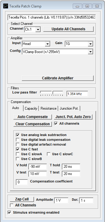
Getting Started > Amplifiers > Tecella Patch Clamp Amplifier Control Panel
The amplifier gain, compensation and current/voltage clamp mode of Tecella patch clamp amplifiers can be set from this control panel.
Select
SetupTecella Patch Clamp
to display the Tecella Patch Clamp control panel.
Voltage-Clamp Mode
Config: Select one of the VCLAMP configurations to set the amplifier into voltage-clamp mode
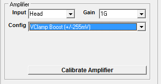
Input: Selects the amplifier input (None = No input, Head = headstage input, VModel = 100 MOhm model cell, IModel = 1 MOhm model cell).
Gain: Selects the headstage feedback resistor.
Current-Clamp Mode
Config: Select one of the ICLAMP configurations to set the amplifier into current-clamp mode
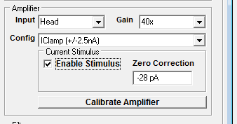
Input: Select Head = headstage input or Head+Model = 10 MOhm model cell in parallel with the input.
Gain: Selects the gain of the voltage channel amplifier.
Select Enable Stimulus to allow current stimuli to be applied to the cell.
Bias Currect Correction: Pico amplifiers produce a small bias current when is selected resulting in a deflection of the cell membrane potential unless compensated for. This can be corrected by observing the shift in membrane potential which occurs when Enable Stimulus is toggle on and off and entering current value into the Zero Correction field until now shift occurs.
Filters
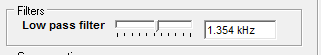
Low pass filter: Slider selects cut-off frequency of Bessel low pass filter.
Compensation
Auto page:
Automatic capacity/leak current compensation.
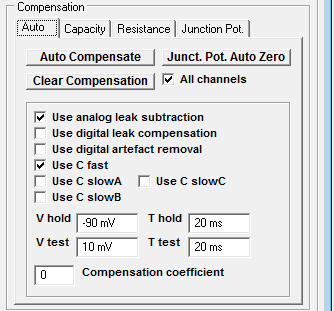
Click Auto Compensate to automatically compensate for pipette/cell capacity and cell leak conduction.
Click Junct. Pot. Auto Zero to compensate for the electrode junction potentials, setting the input current to zero.
Click Clear Compensation to set all compensation to zero.
Options
Tick the Use analog leak subtraction option to use the amplifier analog leak current subtraction circuits in the automatic leak current compensation.
Tick the Use digital leak current subtraction option to use the digital leak current in the automatic leak current compensation.
Tick the Use digital artefact removal option to use the digital artefact function in the automatic leak current compensation.
Tick Apply to all channels to apply automatic compensation to all amplifier channels (only applies to multi-channel amplifiers).
Compensation coefficient: Sets the compensation coefficient factor (0=optimal compensation, >0=under-compensation, <0 = over-compensation).
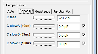
Capacity page:
Capacity compensation settings in use. Can be adjusted by the user or set automatically using Auto Compensate.
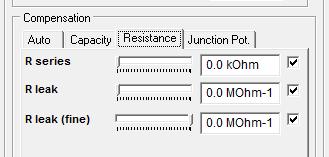
Resistance page:
Cell leak and pipette series resistance compensation settings in use. Can be adjusted by the user or set automatically using Auto Compensate.
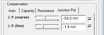
Junction Pot. page:
Electrode junction potential compensation settings in use. an be adjusted by the user or set automatically using Junct. Pot. Auto Zero.
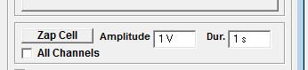
Zap Cell:
Click Zap Cell to apply a voltage pulse of amplitude set by Amplitude and duration set by Dur.
Stimulus Streaming Mode
Select Stimulus Streaming Enabled to generate stimulus pulses as point-by-point waveforms (rather than as sets of discrete step/ramp commands).