Data Files > WCP File Structure
This appendix provides a detailed specification of the internal structure of the WinWCP data file. The WCP data file is designed to store digitised 16 bit integer binary records of analog signals, the associated scaling information required to reconstitute actual signal levels, validation information entered by the user and measurements generated by WinWCP analysis modules.
A WCP file can contain up to 231 separate records, each record containing up to 128 channels, each channel containing a multiple of 256 samples, up to a total of 1048576 for the whole record. Note. All records within a file must be the same size, i.e. same number of channels and samples/channel.
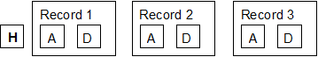
Three kinds of data blocks can exist within the file. The header block contains a list of ASCII-format keywords, detailing the number of records in the file, record size, scaling factors etc. Signal records are stored in sequence after the header block. Each record consists of an analysis block, containing validation and analysis results pertaining to the record, followed by a data block containing the digitised A/D samples. A data file thus has the form:
 ….
….
The beginning of each signal record can be determined as a byte offset from the start of the file using the formula
Offset = HBsize + (Rec#-1)(RABsize + RDBsize)
where HBsize, RABsize and RDBsize are the sizes (bytes) of the header, record analysis and data blocks respectively and Rec# is the record number.
Header Block
The header block contains the information needed to allow a program to determine the size and number of records in the file. The header block can vary in size between 1024 and 16380 byte depending on the number of channels in the file, according to the formula:
HBsize = (Int(Nchans- 1)/8) + 1) x 1024
File parameters are stored as ASCII text in the form of keywords, one word per line, as follows
KEY= <value> <cr> <lf>
where <value> is a number or text depending on the parameter and <cr> <lf> are the carriage return and line feed characters.
A typical header block (from a file with 2 channels) contains the following keywords.
VER=9 WCP data file format version number
CTIME= 19-05-2010 15:15:59.010 Creation date/time
RTIME= 19-05-2010 15:15:60.000 Date/time of start of recording
RTIMESECS= 2000.00 Time of start of recording in seconds (relative to last system boot)
NC=2 No. of channels per record.
NR=50 No. of records in the file.
NBH=2 No. of 512 byte sectors in file header block
NBA=1 No. of 512 byte sectors in a record analysis block
NBD=4 No. of 512 byte sectors in a record data block
AD=5.0000 A/D converter input voltage range (V)
ADCMAX=2047 Maximum A/D sample value
NP=512 No. of A/D samples per channel
DT=.1600 A/D sampling interval (s)
NZ=10 No. of samples averaged to calculate a zero level.
TU=ms Time units
ID= Cell 1 Experiment identification line
Channel scaling factors
YN0=Im Channel 0 name
YU0=nA Channel 0 units
YG0=.167E+04 Channel 0 gain factor mV/units
YZ0=1997 Channel 0 zero level (A/D bits)
YO0=0 Channel 0 offset into sample group in data block
YR0=2
YN1=Vm Channel 1 name
YU1=mV Channel 1 units
YG1=10.0 Channel 1 gain factor mV/bit
YZ1=2048 Channel 1 zero level (A/D bits)
YO1=1 Channel 1 offset into sample group in data block
YR1=0
Waveform measurement settings
TXPERC=0 T.x% decay time settings
PKPAVG=1 No. of points to average before/after for peak measurement
Non-stationary variance settings
NSVCHAN=0 Signal channel to be analysed
NSVALIGN=0 Alignment mode
NSVTYPR=0
NSVS2P=F T = Scale average current to peak before subtraction
NSVCUR0=0 First analysis cursor position
NSVCUR1=0 Second analysis cursor position
ID=
Note that it should not be assumed that the keywords will follow any particular order.
Record Analysis Block
The record analysis block containing a series of internal format variables. It varies in size between 1024 and 16380 byte depending on the number of channels in the file, according to the formula:
RABsize = (Int(Nchans- 1)/8) + 1)+1) x 1024
where Nchans is the number of data channels and Int() means round down to the nearest integer.
The analysis block structure is detailed below:
|
Variable |
Type |
Contents |
|
Record status |
8 x ASCII bytes |
ACCEPTED, REJECTED |
|
Record type |
4 x ASCII bytes |
TEST, LEAK, etc. |
|
Group number |
4 byte floating point |
Record leak subtraction grouping number |
|
Time recorded |
4 byte floating point |
(s) |
|
Sampling interval |
4 byte floating point |
(s) |
|
Max positive limit of A/D voltage range |
4 byte floating point x Nchans |
(V) |
|
Marker |
16 x ASCII bytes |
User entered marker |
|
Values |
4 byte floating point |
Waveform measurement and curve fitting data storage array. |
Data block
The data block contains the digitised signals, stored in the form of 16 bit binary integers. Each A/D sample takes up 2 bytes of space. Its size depends upon the number of data channels in the file
RDBsize = 2 x Nchans x Nsamples per chan
where Nchans is the number of data channels and Nsamples per chan is the number of A/D samples per channel. If there is more than one A/D input channel, samples are interleaved within the data block. For example, for 2 channels,
Y01 Y11 Y02 Y12 ..... Y0nsamples Y1nsamples
Different laboratory interfaces supported by WinWCP return multichannel A/D samples in different orders. The channel interleaving order for a data file is specified by the YOn= channel keyword in the file header block.
The calibrated signal level in the appropriate channel units can be reconstructed using information stored in the file header and the record analysis blocks, using,
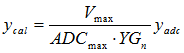
where Vmax the maximum positive limit of the A/D converter voltage range (from record analysis block) ,ADCmax is maximum A/D sample value at Vmax. (header block) and YGn is the calibration factor (Volts/channel units) for channel n (header block).