Transient Measurement Considerations
Cabling
When using the NI 4070/4071/4072 to acquire waveforms, choose your connecting cable carefully. Any unshielded cable or test leads can pick up common electromagnetic and electrostatic interference which corrupts waveform measurements and introduces spurs in the frequency domain. Shielded coaxial cables are often used for waveform measurement. You can use a female-BNC-to-dual-banana-plug adapter, such as Pomona part number 1269, to easily connect the NI 4070/4071/4072 inputs to signal sources using coaxial shielded cable. National Instruments recommends the Belden 83317E shielded cable. Refer to the Belden CDT Incorporated Web site at www.belden.com for information about this cable. The Belden 83317E shielded cable works well for DMM measurements within the 300 kHz bandwidth (3 dB) of the NI 4070/4071/4072 and in situations where BNC connectivity is not required.
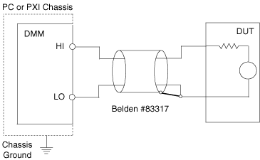
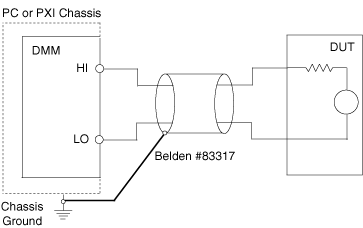
There are two alternative ways to connect the shield. If high frequency (> 1 kHz) common-mode AC signals are present, better results can be obtained if the shield is connected to the DMM LO terminal. If no common-mode AC signal is present or if the common-mode AC signal is low (< 100 mV), then connecting the shield to PXI chassis ground is preferable. The following figures show the DMM connected to a device under test (DUT) with the Belden 83317E cable.
As shown in the figure below, the best HI signal shielding results with a common-mode AC signal > 1 kHz. The shield potential must remain within 42 VAC/DC of LO:

As shown in the figure below, good shielding results if common-mode AC signals are less than 100 mV, and the shielding is safest if a large DC common-mode voltage is present.

 |
Caution Always observe proper safety practices when connecting to signals. Be aware that if the LO signal is connected to a source of hazardous voltage (either AC or DC) then any exposed BNC connector shells or shields connected to this voltage will also be at this hazardous voltage. |
Slew Rate Limitations
The NI 4070/4071/4072 can measure almost any signal within its 300 kHz bandwidth. However, some signals may have enough high-frequency energy to introduce significant distortion. In general, the rate of change of the input signal voltage or current, also known as its slew rate, should stay below the following limits to avoid excessive distortion:
| Input Range | Maximum Slew Rate |
|---|---|
| 300 V (NI 4070/4072 only), 1000 V (NI 4071 only) | 2000 V/µs |
| 100 V | 200 V/µs |
| 10 V | 20 V/µs |
| 1 V | 2 V/µs |
| 100 mV | 0.4 V/µs |
| 1 A | 8 A/µs |
| 200 mA | 0.8 A/µs |
| 20 mA | 0.8 A/µs |
If you suspect your slew rate may be too high, you can switch to a higher range to see if the waveform shape changes significantly.